


LIMITATIONS
These units must be installed in accordance with all national
andlocal safetycodes. Ifno localcodes apply,installationmust
conform with the appropriate national codes. See Table 1 for
Unit Application Data. Units are designed to meet National
Safety Code Standards. If components are to be added to a
unit to meet local codes, they are to be installed at the dealer's
and/or the customer's expense.
LOCATION
Use the following guidelines to select a suitable loca
-
tion for these units.
1.
The condensing unit is designed for outdoor installation
only. The condenserfans arethe propellertype and arenot
suitable for use with duct work.
2. The condensing unit and the evaporator blower should be in-
stalled as close together as possible and with a minimum
number of bends in the refrigerant piping. Refer to “REFRIG-
ERANT PIPING” for additional information.
3. The condensing unit should not be installed where normal
operating sounds may be objectionable. On either rooftop
orground levelinstallations, rubberpadding canbeapplied
between the base rails and their supports to lessen any
transmission of vibration.
ROOF-TOP LOCATIONS
Becarefulnotto damagetheroof. Consultthebuildingcontrac
-
tororarchitectiftheroofisbonded.Choosealocationwith ade
-
quate structural strength to support the unit.
The condensing unit must be mounted on solid level supports.
The supports can be channel iron beams or wooden beams
treated to reduce deterioration.
A minimum of two (2) beams are required to support each unit.
The beams should: (1) Be positioned perpendicular to the roof
joists. (2) Extend beyond the dimensions of the unit to distribute
the load on the roof. (3) Be capable of adequately supporting the
entire unit weight. Refer to Center of Gravity and Point Load Fig
-
ures and Physical Data Table for load distribution and weights.
Thesebeamscanusually besetdirectlyon theroof.Flashingis
not required.
NOTE: On bondedroofs,checkforspecial installationrequire
-
ments.
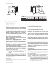
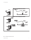
GROUND LEVEL LOCATIONS
The units must be installed on a one-piece level concrete slab
with a minimum thickness of 4 inches. The length and width
should be at least 6 inches greater than the units overall base
dimensions. Refer to Figure 4.
Footers under the slab that extend below the frost line is rec
-
ommended. Anystrain on therefrigerant lines maycause a re
-
frigerant leak. The slab should not be tied to the building
foundationbecause noiseand vibrationwill telegraphinto your
structure.
A unit can also be supported by concrete piers. These piers
should (1) extend below the frost line, (2) be located under the
unit's four corners, and (3) be sized to carry the entire unit
weight. Refer to Figure 1 and Table 2 for the center of gravity
and unit weight.
CAUTION: Care should be taken to protect the unit from tam
-
pering and unauthorized persons from injury.
Screws on access panels will prevent casual tam
-
pering. Additional safety precautions such as
fences around the unit or locking devices on the
panels may be advisable. Check local authorities
for safety regulations.
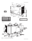
RIGGING AND HANDLING
Exercise care when moving the unit. Do not remove any pack
-
aging until the unit is near the place of installation.
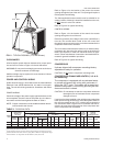
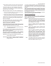
Rig the unit by attaching nylon straps with hooks to the lifting
holes provided in the base rails. Spreaders, whose length ex
-
ceeds the largest dimension across the unit, MUST be used
across the top of the unit if the rigging height above the top of
the unit is less than 5 feet. See Figure 2.
WARNING:Donotuse strapsunderthe unitorthrough thefork
liftslotsforliftingpurposes.Sharpmetaledgescan
damage the straps and could result in personal in
-
jury or equipment damage.
BEFORE LIFTING A UNIT, MAKE SURE THAT ITS WEIGHT
IS DISTRIBUTED EQUALLY ON THE STRAPS SO THAT IT
WILL LIFT EVENLY.
Units may also be moved or lifted with a fork-lift. Slotted open
-
ings in the base rails are provided for this purpose. The 7-1/2
ton unit may be lifted from either the LH or RH side - under the
unit.
LENGTHOFFORKSMUSTBEAMINIMUMOF42"for 7-1/2ton
units or a MINIMUMOF 54" for 10 ton units when liftingacross
the long dimension.
Remove the nesting brackets from the four corners on top of
the unit. All screws that areremoved to take these brackets off
must be replaced on the unit.
035-15407-002-B-0404
Unitary Products Group 3
INSTALLATION
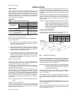
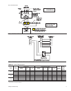
MODEL HCE090,120 & 150
Voltage Variation
1
Min. / Max.
208/230-3-60 187 / 252
460-3-60 432 / 504
575-3-60 540 / 630
380/415-3-50 342 / 456
Ambient Air on Condenser Coil
Min. / Max.
45°F / 115°F
2
Suction Pressure at Compressor and
Corresponding Temp. at Saturation
Min. / Max.
57.5 psig / 90.0 psig
32.0°F / 53.5°F
1
Rated in accordance with ARI Standard 110, utilization range “A”.
2
These units can operate at an ambient temperature of 120°F providing the wet bulb
temperature of the air entering the evaporator coil does not exceed 67°F.
NOTE: Refer to page 7 for refrigerant piping limitations.
TABLE 1 - UNIT APPLICATION DATA
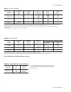
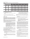
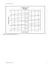
FIG. 1 - CENTER OF GRAVITY
Unit
Dim. (in.)
ABCD
7
Ton 42 31 19 11
10 Ton 70 32 30 15
Ton 32