


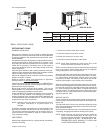
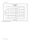

CLEARANCES
All units require certain minimum clearances for proper opera-
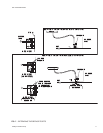
tion and service. Refer to Figure 4 for these clearances.
WARNING:Do not permit overhanging structures or shrubs to
obstruct condenser air discharge.
Additional height may be required for snow clearance if winter
operation is expected.
POWER AND CONTROL WIRING
Install electrical wiring in accordance with the latest National
Electrical Code (NFPA Standard No. 70) and/or local regula
-
tions. The unit should be grounded in accordance with these
codes.
POWER WIRING
Check the voltage of the power supply against the data on the
unit nameplate. Check the size of the power wire, the discon
-
nect switch and the fuses against the data on Table 3.
NOTE: Copper conductors must be installed between the dis
-
connect switch and the unit.
Refer to Figure 4 for the location of the power wire access
openingthrough thefront ofthe unit.This openingwill requirea
field-supplied conduit fitting.
The field-supplied disconnect switch must be suitable for an
outdoor location. Although it should be installed near the unit,
do NOT
secure it to the unit cabinet.
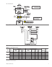
Refer to Figure 3 for typical field wiring.
CONTROL WIRING
Refer to Figure 4 for the location of the control wire access
opening through the front of the unit.
Route the necessary low voltage control wires (18 AWG min.)
from the TB1 terminal block inside of the unit control box
through this access opening to the room thermostat and to the
evaporator blower motor controller.
The room thermostat should be located on an inside wall ap
-
proximately 56" above the floor where it will not be subject to
drafts, sun exposure or heat from electrical fixtures or appli
-
ances. Follow manufacturer's instructions enclosed with ther
-
mostat for general installation procedure.
Refer to Figure 3 for typical field wiring.
COMPRESSOR
Units are shipped with compressor mountings factory-
adjusted and ready for operation.
CAUTION: Do Not loosen compressor mounting bolts.
COMPRESSOR CRANKCASE HEATER (7-1/2 & 10
ton units only)
The compressor is equipped with a crankcase heater
to prevent refrigerant from mixing with crankcase oil
during the “OFF” cycle. The heaters will be energized
when the compressor is not running providing the unit
disconnect switch is closed.
CAUTION: Do not attempt to start the compressor without at
least eight hours of crankcaseheat or compressor
damage will occur.
Ifaunithas justbeeninstalled ortheunit disconnectswitchhas
beenopen foralong periodof time,movethe systemswitchon
the room thermostat to the “OFF” position before closing the
unit disconnect switch. Eight hours of crankcase heat are re
-
quired to drive the liquid refrigerant out of the compressor bef
-
ore the compressor can be started.
035-15407-002-B-0404
4 Unitary Products Group
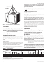
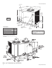
5 F T . M I N .
FIG. 2 - TYPICAL RIGGING (7-1/2 Ton Shown)
Model
HCE
Compressor
(Tandem on
150 only)
Condenser Unit
Weight
(Lbs.)
Charge,
Lbs.-Oz.
(Refrigerant-22)
Fan (Propeller) Fan Motor
1
Coil
3
Rating
(Tons)
Cap.
(Stages)
Qty.
Dia.
(in.)
Nom.
CFM
Blades
Qty. HP RPM Rotation
2
Face
Area
(Ft.
2
)
Finned
Length
(in.)
Rows
High
Ship.Oper. Holding Oper.
4
Qty.
Pitch
(Deg.)
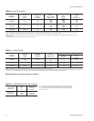
090 7-1/2 1 1 24 4677 3 29 1 3/4 1120 CW 18.7 90 30 365 360 1 - 12 12 - 0
5
120 10 1 2 24 8034 3 27 2 1/2 1110 CCW 23.8 96 36 435 430 2 - 4 18 - 6
150 12-1/2 1 2 24 7950 3 27 2 1/2 1110 CCW 23.8 96 36 515 510 2 - 4 19 - 5
1
These PSC motors are directly connected to the condenser fans and have inherent protection, ball bearings and a 48 frame.
2
When viewing the shaft end of the motor.
3
These condenser coils have 2 rows of 3/8” OD copper tubes and 16 aluminum fins per inch.
4
Includes matched indoor blower unit but no piping. Refer to Table 6 for refrigerant line charge.
5
Add an additional 1 lb. charge when used with KEU120 (10 ton) indoor units.
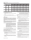
TABLE 2 - PHYSICAL DATA