


NOTE: Use only copper tubing that has been especially
cleaned and dehydrated for refrigerant use. If the tub
-
ing has been open for an extended period of time, it
should be cleaned before being used.
NOTE:
1. The matched air handlers are shipped with a small R-22
charge and they should be checked for leaks before instal
-
lation. Drill a small hole through the sealing cap or disc in
both the liquid and suction connection. If there is a pres
-
sure release, the evaporator has no leaks and you can pro
-
ceed with installation. If the charge has been lost, the coils
should be leak tested and the necessary repairs made.
2. Move the dry nitrogen supply from the access port on the
liquid line service valve of the outdoor unit to the hole
through the vapor disc on the indoor unit.
3. Unbraze the coil's liquid line disc while maintaining a flow of
dry nitrogen across the connection and through the hole in
the liquid line disc.
4. After the disc has been removed, burnish the external sur-
faces and clean the internal surfaces as outlined above.
5. Move the dry nitrogen supply back to the access port on the
liquid line service valve.
6. Braze the liquid line to the liquid connection on the indoor
unit while maintaining a minimum flow of dry nitrogen
through the liquid line, the indoor coil and the hole in the va-
por disc.
7. Unbraze the disc on the vapor connection of the indoor unit
while maintaining the flow of dry nitrogen.
8. After the disc has been removed, burnish the external sur
-
faces and clean the internal surfaces as outlined above.
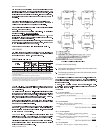
1. Make sure that the vapor line service valve on the outdoor
unit is front-seated and closed with its valve stem in the
maximum clockwise position.
Drill a small hole through the disc before unbrazing it to per
-
mit a flow of dry nitrogen through the connection while its
being unbrazed.
Move the dry nitrogen supply to the access port on the va
-
por line service valve of the outdoor unit.
Unbraze the disc on the vapor line connection of the out
-
door unit while maintaining a minimum flow of dry nitrogen
through the access port of the vapor line service valve and
the hole in the vapor disc.
After the disc has been removed, burnish the external sur
-
faces and clean the internal surfaces of the vapor connec
-
tion and the vapor piping.
EVACUATING AND CHARGING
NOTE:
CAUTION: Do not charge liquid refrigerant through the com
-
pressor suction connection.
CAUTION: Do not attempt to start the compressor without at
least 8 hours of crankcase heat or compressor
damage will occur.
Method 1: Determine the total weight of the refrigerant for the
total system by adding the required charge for the
outdoor unit, the indoor unit and the refrigerant
lines using information in Tables 2 (Physical Data)
and 6 (Refrigerant Line Charge). Using the charg
-
ing procedures outlined above, weighthe required
amount of refrigerant charge into the unit.
Method 2: Install a field supplied moisture indicating sight
glass in the liquid line between the filter-drier and
the evaporator coil.
Using the charging procedure outlined above,
charge refrigerant until the moisture indicating
sight glass is clear. Add approximately 1 extra
pound of refrigerant to assure a liquid refrigerant
seal at the expansion valve under all operating
conditions. Block the flow of the condenser air, if
necessary, to assure a head pressure of 280 psig
during the charging procedure.
NOTE:
Unitary Products Group 9
035-15410-002-B-0404