LINE SIZING
°
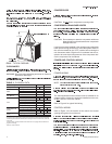
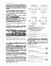
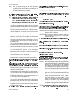
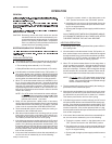
Oil return will be critical during:
The cooling cycle when theoutdoor unit is above the indoor
unit (detail 1 of Figure 5).
The heatingcycle when the indoorunit is abovethe outdoor
unit (detail 4 of Figure 5).
EXAMPLES:
#1 - 7-1/2 Ton System
125 feet of 1-3/8" OD, type “L” copper tubing
(125 feet x 1.6 psi/100 feet)
...........................................
2.0 psi
Fitting*
....................................................................................
0.4 psi
Vapor Line Pressure Drop = 2.4 psi
#2 - 10 Ton System
89 feet of 1-3/8" OD, type “L” copper tubing
(89 feet x 2.8 psi/100 feet)
.............................................
2.5 psi
Fitting*
....................................................................................
0.5 psi
Vapor Line Pressure Drop = 3.0 psi
#3 - 7-1/2 Ton System
51 feet of 1-1/8" OD, type “L” copper tubing (vertical)
(51 feet x 4.7 psi/100 feet)
.............................................
2.4 psi
6 feet of 1-3/8" OD, type “L” copper tubing (horizontal)
(6 feet x 1.6 psi/100 feet)
...............................................
0.1 psi
Fitting*
....................................................................................
0.5 psi
Vapor Line Pressure Drop = 3.0 psi
#4 - 10 Ton System
29 feet of 1-1/8" OD, type “L” copper tubing (vertical)
Unitary Products Group 7
035-15410-002-B-0404
1
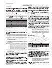
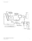
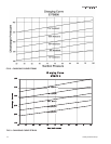
Based on Refrigerant-22 at the nominal cooling capacity of the system, a liquid temperature
of105°Fandavaportemperatureof40°F.Sincerefrigerantflowrateswillbealittlelowerat
thenominalheatingcapacityofeachsystem,liquidlinefrictionlossshouldalwaysbebased
on cooling operation.
2
These friction losses do not include any allowance for fittings.
3
Thetotalpressuredropoftheliquidlineforbothfrictionandverticalrisemustnotexceed40
PSI. If the pressure drop exceeds 40 PSI, the liquid refrigerant could flash before it reaches
theexpansionvalve.Thisflashingwillnotonlycauseerraticvalveoperationandpoorsystem
performance, but could also damage the expansion valve.
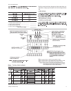
TABLE 4
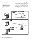
FIG. 5 - FIELD PIPING DIAGRAMS