


GENERAL
CAUTION: Reversing valves and check valves are precise
mechanical devices and will not tolerate any me
-
chanical abusesuch as hammering. Ifa refrigerant
system isn't properly cleaned after a compressor
burn-out, scale may build up at these devices and
prevent them from operating properly.
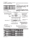
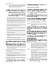
SYSTEM SEQUENCE OF OPERATION
COOLING OPERATION
The following controls will be energized through terminal O
on the thermostat to put the system in the cooling mode.
•
The reversing valve solenoid (7-1/2 Ton units)
•
Relay 2Rand the reversing valvesolenoid (10 Ton units)
If the fan switch on the thermostat is in the “ON” position, in-
door section blower motor contactor 10M will be energized
through terminal G to provide continuous blower operation.
If the switch is in the “AUTO” position, the blower will oper-
ate only when the thermostat calls for cooling operation.
3. When TC1 of the thermostat closes on a demand for cool
-
ing, a circuit is made from terminal Y through the defrost
control board and safety switches to energize contactor 1M
and relay 1R, starting the compressor. Contactor 2M is en
-
ergized through the NO contacts of 1R-2 and the NC con
-
tacts of K2 on the defrost control board in order to start the
outdoor fan motor(s).
NOTE: On 10 Ton
units, both outdoor fan motors will oper
-
ate if the ambient temperature is above 65
F. If the
ambient temperature falls below 65
F, control 3TH
will shut down the No. 1 fan motor.
4. Relay 1R also prevents the 10KW portion of accessory
electric heat referenced as standby electric heat frombeing
utilized whenever the compressor is in operation. This part
of the circuit is covered under HEATING OPERATION.
5. The thermostat will cycle the unit to satisfy the cooling re
-
quirements of the conditioned space.
6. After the unit has shutdown from a cooling cycle or a power
interruption, the anti-short cycle feature of the defrost con
-
trol board will not permit the unit to restart for 5 minutes.
This feature prevents the unit from short cycling.
7. If the discharge pressure reaches 430 psig, the HP control
will open and the defrost controlboard will lock out the com
-
pressor. If the discharge temperature reaches 255°F, 2TH
thermostat will open and the defrost control board will lock
out the compressor. If the suction pressure falls to 7 psig,
the low pressure switchwill open and the defrostcontrol will
lock out the compressor.
8. If the control that caused the lockout has automatically re
-
set, the unit can be restarted by one of the following:
a. Turning the system switch on the thermostat to the
“OFF” position and back to the “COOLING” position.
b. Increasing the set point on the thermostat above the
temperature in the conditioned space and then return
-
ing it to its original setting.
c. Opening and closing thepower supply main disconnect
switch.
IN ALL THREE RESET METHODS DESCRIBED ABOVE,
A FIVE MINUTE TIME DELAY WILL TAKE PLACE AFTER
THE RESET BEFORE THE UNIT WILL RESTART.
HEATING OPERATION
1. Reversing valve is de-energized and the system will be in
the heating mode.
2. If the fan switch onthe thermostat is in the “ON”position, in
-
door section blower motor contactor 10M will be energized
through terminal G to provide continuous blower operation.
If the switch is in “AUTO” position, the blower will operate
only when thermostat calls for heating operation.
3. When TH1 of the thermostat closes for first-stage heat, a
circuit is made from terminal Y through the defrost control
board and safety switches to energize contactor 1M and
start the compressor. Contactor 2M is energized through
the NO contacts 1R-2 and the NC contacts of K2 on the de-
frost controlboard which will start theoutdoor fan motor(s).
NOTE: On 10 Ton
units, if 3TH thermostat opens due to
outdoor ambient temperature being below 65
F,
the No. 1fan motor willcontinue to operate through
the NC contacts of relay 2R.
4. The thermostat will cycle the unit to satisfy the heating re
-
quirements of the conditioned space.
5. After the unit has shutdown from a heating cycle or a power
interruption, the anti-short cycle feature of the defrost con
-
trol board will not permit the unit to restart for 5 minutes.
This feature prevents the unit from short cycling.
6. If the discharge pressure reaches 430 psig, the HP control
will open andthe defrost control board willlock out the com
-
pressor. If the discharge temperature reaches 255°F, 2TH
thermostat will open and the defrost control board will lock
out the compressor. If the suction pressure falls to 7 psig,
the low pressureswitch will openand the defrostcontrol will
lock out the compressor.
7. If the control that caused the lockout has automatically re
-
set, the unit can be restarted by one of the following:
a. Turning the system switch on the thermostat to the
“OFF” position and back to the “HEATING” position.
b. Decreasing the set point on the thermostat below the
temperature in the conditioned space and then return
-
ing it to its original setting.
c. Opening and closing thepower supply main disconnect
switch.
035-15410-002-B-0404
Unitary Products Group 13
OPERATION