


CLEARANCES
WARNING: Do not permit overhanging structures or shrubs to
obstruct air discharge.
COMPRESSORS
CAUTION:
Do Not
loosen compressor mounting bolts.
COMPRESSOR CRANKCASE HEATER
CAUTION: Do not attempt to start the compressor without at
least eight hours of crankcase heat or compressor
damage will occur.
If a unit hasjust been installed or theunit disconnect switch has
been open for a long period of time, move the system switch on
the room thermostat to the “OFF” position before closing the
unit disconnect switch. Eight hours of crankcase heat are re
-
quired to drive the liquid refrigerant out of the compressor bef
-
ore the compressor can be started.
POWER AND CONTROL WIRING
POWER WIRING
NOTE:
The field-supplied disconnect switch must be suitable for an
outdoor location. Although it should be installed near the unit,
do NOT
secure it to the unit cabinet.
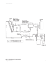
Refer to Figure 3 for typical field wiring.
CONTROL WIRING
Refer to Figure 4 for the location of the control wire access
opening through the front of the unit.
4 Unitary Products Group
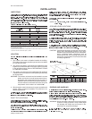
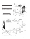
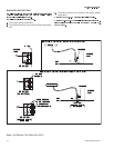
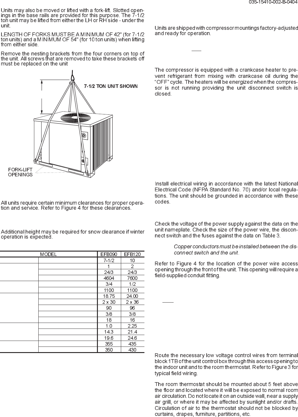
FIG. 2 - TYPICAL RIGGING
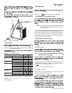
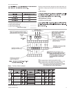
Compressor
1
Rating, (Tons)
Fans
Quantity
Diameter, (In.)/No. Blades
Nominal CFM
Fan Motors
2
HP
RPM
Coil
Face Area, (Sq. Ft.)
Rows Deep x Rows High
Finned Length, (In.)
Tube (Copper) OD - inches
Fins (Aluminum) per inch
Refrigerant-22
(Lbs.)
Holding Charge
Operating Charge
3
Pumpdown Capacity
4
Unit Weight
(Lbs.)
Shipping
Operating
1
These compressors are fully hermetic.
2
ThesePSCmotorsaredirectlyconnectedtotheoutdoorfansandhaveinherentprotection,
ballbearingsanda48frame.Rotation(whenviewingtheshaftendofthemotor)-090=CW,
120=CCW.
3
Includesoutdoorunitandmatchedindoorblowerunit,butnopiping.RefertoTable6forre-
frigerant line charge.
4
Based on a 95°F ambient.
TABLE 2 - PHYSICAL DATA
5 F T . M I N .