


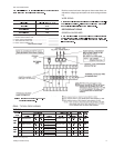
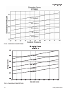


(29 feet x 8.0 psi/100 feet)
.............................................
2.3 psi
7 feet of 1-3/8" OD, type “L” copper tubing (horizontal)
(7 feet x 2.8 psi/100 feet)
...............................................
0.2 psi
Fitting*
....................................................................................
0.5 psi
Vapor Line Pressure Drop = 3.0 psi
*
Determinethepressuredropofthefittingsforeachinstallation- DONOTusetheestimated
values as shown in the above examples.
°
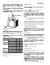
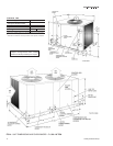
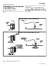
SERVICE VALVES
EXTENDING THE SERVICE PORTS
1. Loosen the screws securing the service ports in shipping
position. (See FIG 6).
2. Push the service ports through the corner post.
3. Tighten thescrews to secure theservice portsfor installation.
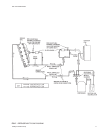
INSTALLATION
Since the condensing units are shipped with a holding charge
of Refrigerant-22, they can be checked for a refrigerant leak by
depressing the stem on either of the service ports that extend
through the cabinet. As soon as some internal pressure is re
-
lieved release the stem. DO NOT release the entire holding
charge.
CAUTION: When making a braze connection, wrap a wet rag
around all tubinginside the unit toprevent damage
to the other components.
Dry nitrogen should always be supplied through a
connection while it is being brazed or unbrazed
because the temperature required to make or
break a brazed joint is sufficiently high to cause
oxidation of the copper unless an inert atmos
-
phere is provided. The flow of nitrogen should be
continued until the joint has cooled.
WARNING: The dry nitrogen must always be supplied through
a pressure regulating valve.
Make sure the refrigerant in the line has been recovered
and that the liquid service valve on the unit is front-seated
and closed. The valve stem should be turned to its maxi-
mum clockwise position.
Drill a small hole throughthe disc before unbrazing it to per-
mit a flow of dry nitrogen through the connection while it is
being unbrazed.
WARNING: This hole is also required to prevent the internal
pressure from building up as the disc is being un
-
brazed and from blowing the disc off.
This warning applies to any disc being removed
from a service valve, coil connection, etc.
Remove the cap from the 1/4" access port on the liquid line stop
valve.
Connect a supply of dry nitrogen to this access port.
Unbraze the copper disc from the liquid connection while
maintaining a minimum flow of dry nitrogen through the
connection.
Burnish the external surfaces of the liquid connection on
the outdoor unit and the end of the field-supplied piping be
-
ing used for the liquid line.
NOTE:
2. Carefully clean the internal surfaces of the above. Any par
-
ticles left on these surfaces may lead to a future system
malfunction.
8 Unitary Products Group
1
All horizontal vapor lines should be level since the refrigerant flows in both directions.
2
Allvaporlineswithaverticalriseexceeding50feetshouldhaveanintermediatetrap.Small
radiustrapswillprovidedrainagepointsfortheoilwhichisintheriserwhenthecircuitis
deactivated.Whenthecircuitisreactivated,theoilwillbereturnedtothecompressormore
quickly and in smaller slugs.
3
Everyvaporrisergreaterthan5feetinheightshouldhaveasmallradiustrapatthebottom.
4
BasedonRefrigerant-22atthenominalcoolingcapacityofthesystem,avaportemperature
of40°Fandaliquidtemperatureof105°F.Sincerefrigerantflowrateswillbealittlelowerat
thenominalheatingcapacityofeachsystem,vaporlinefrictionlossshouldalwaysbebased
on cooling operation.
5
Althoughvaporlinesshouldbesizedforafrictionlossequivalenttoa2°Fchangeinsaturation
temperature (or approximately 3 psi), sizing the lines for the proper return of oil is more
important.
6
These friction losses do not include any allowance for fittings. Only use a 1-1/8" riser when
the indoor unit is above the outdoor unit.
TABLE 5
1
Charges are based on 40°F suction temperature and 105°F liquid temperature.
2
Type “L” copper tubing.
TABLE 6