


CRANKCASE HEATER
CAUTION: DO NOT ATTEMPT TO START THE COMPRES
-
SOR WITHOUT AT LEAST 8 HOURS OF
CRANKCASE HEAT OR COMPRESSOR DAM
-
AGE WILL OCCUR.
PRE-START CHECK
1. Have sufficient clearances been provided?
2. Has all foreign matter been removed from the interior of the
unit (tools, construction or shipping materials, etc.)?
3. Have the outdoor fans been rotated manually to check for
free rotation?
4. Are all wiring connections tight?
5. Does the available power supply agree with the nameplate
data on the unit?
6. Have the fuses, disconnect switch and power wire been
sized properly?
7. Are all compressor hold-down nuts properly secured?
8. Are any refrigerant lines touching each other or any sheet
metal surface? Rubbing due to vibration could cause a re-
frigerant leak.
9. Are there any visible signs of a refrigerant leak, such as oil
residue?
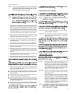
10. Is any electrical wire laying against a hot refrigerant line?
Keep in mind that this unit has a reverse cycle and that dif-
ferent lines will be hot during the “HEAT” and “COOL” cy-
cles. Only two lines will remain cool for all cycles - the line
between the compressor and the accumulator and the line
between the accumulator and the reversing valve.
INITIAL START-UP
1. Supply power to the unit through the disconnect switch
prior to starting the compressor.
2. Move the system switch on the room thermostat to the
“COOL” position, and lower its set point to energize both
the compressor and the reversing valve. Cool air will be
supplied to the conditioned space.
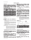
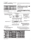
Check the compressor amperage. It should not exceed
the RLA rating printed on the unit data plate or in Table 3
unless the ambient temperature is above 105°F.
4. Move the system switch on the room thermostat to the
“HEAT” position, and increase the set point of the room
thermostat until heating is required. The compressor will
run, but the reversing valve will be de-energized. Warm air
will be supplied to the conditioned space.
5. Check theoperation of the indoorunit per Form515.41-N2.
6. Check the entire system for refrigerant leaks.
7. Check for any abnormal noises and/or vibrations, and make
the necessary adjustments to correct (e.g. fan blade touching
shroud, refrigerant lines hitting on sheet metal, etc.)
8. After the unit has been operating for several minutes, shut
off the main power supply at the disconnect switch and in
-
spect all factory wiring connections and bolted surfaces for
tightness.
SAFETY FEATURES
1. All outdoor fan motors have inherent protection with auto
-
matic reset.
2. Every compressor is internally protected against excessive
current and temperatureby a linebreak motor protector thatis
mounted inside the compressor housing and is connected
between each winding and the common terminal.
This motor protector will interrupt power to the compressor
if any of the following overload conditions occur:
a. primary single phasing
b. locked rotor
c. compressor overload
d. insufficient motor cooling
This type of motor protection works even with the contac-
tor welded closed.
3. Every compressor is protected by crankcase heaters to
prevent refrigerant from accumulating in the crankcases of
the compressor during an “OFF” cycle.
4. Outdoor fan motors and the secondary of the control trans
-
former are grounded.
5. A fusible plug on the top of the suction line accumulator
serves as a high temperature/high pressure relief device.
035-15410-002-B-0404
Unitary Products Group 15
START-UP
CAUTION:
DO NOT ATTEMPT TO START THE COMPRESSOR
WITHOUT AT LEAST 8 HOURS OF CRANKCASE HEAT OR
COMPRESSOR DAMAGE WILL OCCUR.
CLEANING
LUBRICATION
REPLACEMENT PARTS
NOTICE TO OWNER
MAINTENANCE
SECURE OWNER'S APPROVAL: When the system is functioning properly, secure the owner's approval. Show
him the location of all disconnect switches and the thermostat. Teach him how to start and stop the unit, how to adjust
temperature settings within the limitations of the system, how the defrost cycle is controlled and how the anti-cycle timer
operates.