


107272-UIM-B-1105
8 Unitary Products Group
DUCT CONNECTORS
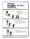
INSTALLATION OF SCREW ATTACHMENT DUCT
CONNECTOR
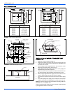
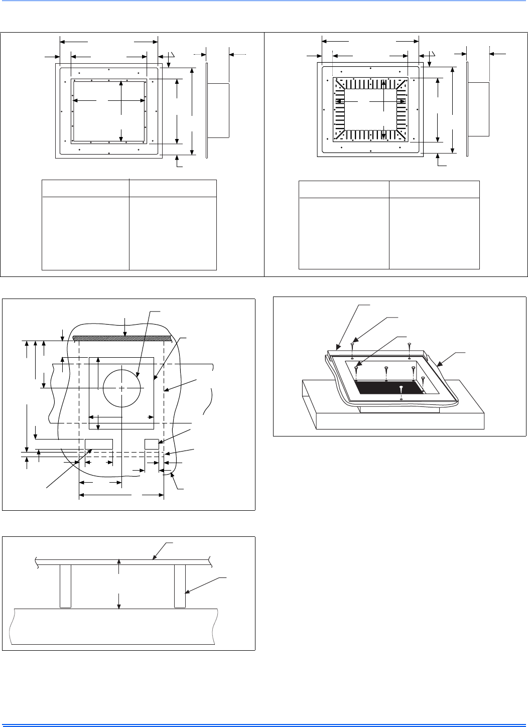
1. Make floor cut out as shown in Figure 8.
2. Determine the depth of the floor cavity from the surface of the floor
to the top of the supply air duct and select the appropriate duct
connector from the chart.
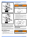
3. Place locating bracket (supplied with the duct connector) to the
back edge of the floor opening. See Figure 10.
4. Apply a water based duct sealant to the 1/2 in (1.3 cm) supply duct
attachment flange of the duct connector.
5. Determine which of the four positions the duct connector best cen-
ters over the supply duct and insert it through the floor cut-out.
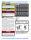
6. When properly aligned with the supply duct, secure the duct con-
nector to the floor with nails, flat head screws or staples.
7. Use screws as required to secure the duct connector to the supply
duct.
8. Cut out the opening to the supply duct. If sealant was not used, the
installer should tape the mating flanges to provide a good air seal.
NOTE: Duct sealant and tape must be classified as meeting HUD Stan-
dard 3280.715, U.L. Standard 181A.
If tape is used to provide a better air seal, it should be a type approved
by the applicable national or local codes.
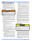
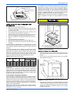
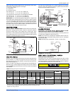
FIGURE 7: Duct Connector Dimensions
2-3/8
(6.0 cm)
12
(30.5 cm)
13
(33.0 cm)
11
(27.9 cm
18-3/4 (47.6 cm)
14 (35.6 cm)
SEE
CHART
DUCT CONNECTOR
PART NUMBER
DUCT CONNECTOR
DEPTH
7990-6011
7990-6021
7990-6041
7990-6061
7990-6071
7990-6081
7990-6101
7990-6121
1” (2.5 cm)
2” (5.7 cm)
4-1/2” (11.4 cm
6-1-2” (16.5 cm)
7-1/2” (19.0 cm)
8-1/2” (21.6 cm)
10-1/4” (26.0 cm)
12-1/4” (21.1 cm)
DUCT CONNECTOR DIMENSIONS
2-3/8
(6.0 cm)
18-3/4
(47.6 cm)
4-3/8
(11.1 cm)
2-3/8
(6.0 cm)
12
(30.5 cm)
13
(33.0 cm)
11
(27.9 cm
18-3/4 (47.6 cm)
14 (35.6 cm)
SEE
CHART
DUCT CONNECTOR
PART NUMBER
DUCT CONNECTOR
DEPTH
1” (2.5 cm)
2” (5.7 cm)
4-1/2” (11.4 cm
6-1-2” (16.5 cm)
7-1/2” (19.0 cm)
8-1/2” (21.6 cm)
10-1/4” (26.0 cm)
12-1/4” (21.1 cm)
DUCT CONNECTOR DIMENSIONS
2-3/8
(6.0 cm)
18-3/4
(47.6 cm)
4-3/8
(11.1 cm)
7990-6211
7990-6221
7990-6241
7990-6261
7990-6271
7990-6281
7990-6301
7990-6321
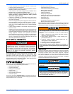
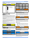
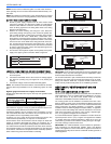
FIGURE 8: Recommended Floor Cut-out
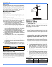
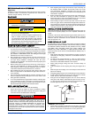
FIGURE 9: Duct Connector Depth
2-3/4 (7.0 cm)
Min.
23-1/4 (59.1 cm)
20-1/2 (52.1 cm)
9-7/8
(25.1 cm
1-3/8
(3.5 cm)
6-3/8
(16.2 cm)
9-3/4
24.8 cm)
20
(50.8 cm)
1-1/8
(2.9 cm)
15
(38.1 cm)
15
(38.1 cm)
1
Rear Wall
of Enclosure
Ceiling Cut-Out
For Roof Jack
Floor Cut-Out
For Duct
Connector
Floor
Future
Refrigerant
Line Entrance
Front Panel
of Furnace
3-1/4
(8.3 cm)
Furnace
Outline
Optional Gas
or Electric
Entrance
2-1/8 (5.4 cm)
Duct Connector
Depth
Floor
Floor
Joist
Supply Duct
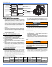
FIGURE 10: Duct Connector Screw Attachment
Locator Bracket
Nails, Flat Head Screws
or Staples
Screws
Floor
Supply Duct