


107272-UIM-B-1105
4 Unitary Products Group
CHECK CERTIFICATIONS / APPROVALS
• Underwriters Laboratories has certified this burner to comply with
ANSI/UL 296 and has listed it for use with #1 or #2 fuel oil as
specified in ASTM D396. Low sulfur #1 and #2 fuel oils reduce
heat exchanger deposits with all burners compared to the stan-
dard fuels. Reduced deposits may extend the service interval for
cleaning and improve the efficiency of the appliance over time.
Low sulfur fuels reduce particulate and oxides of nitrogen emis-
sions as well. The Oil Heat Manufacturers’ Association recom-
mends these fuels as the preferred fuels for this burner.
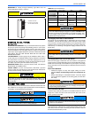
• State and local approvals are shown on burner rating label (See
Figure 1).
• All oil burners must be installed in accordance with the regula-
tions of the latest revision of the National Fire Protection Associa-
tion Standard NFPA 31 and in complete accordance with all local
codes and authorities having jurisdiction. Regulation of these
authorities take precedence over the general instructions pro-
vided in this installation manual.
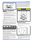
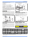
FURNACE LOCATION AND CLEARANCES
The furnace shall be located using the following guidelines:
1. The furnace should be located where the roof jack can be installed
without major modifications to the roof of the structure.
2. As centralized with the air distribution as possible.
3. Where there is access to fresh air particularly when the blend air
accessory will be installed.
4. Where it will not interfere with proper air circulation in the confined
space.
5. Where the outdoor section of the roof jack will not be blocked or
restricted. Refer to “VENT CLEARANCES” located in SECTION VI
of these instructions. These minimum clearances must be main-
tained throughout the installation.
6. Where the unit will be installed in a level position with no more than
1/4” (0.64 cm) slope side-to-side and front-to-back to provide a
proper roof jack connection and seal.
Installation in freezing temperatures:
1. Furnace shall be installed in an area where ventilation facilities
provide for safe limits of ambient temperature under normal oper-
ating conditions. Ambient temperatures below 32º F (0º C) may
result in the vent temperature falling below 260º F (127º C) at any
point in the vent pipe. Vent temperatures below 260º F (127º C)
will cause the flue products in the vent pipe to condense causing
the vent pipe to deteriorate rapidly.
2. Do not allow return air temperature to be below 55º F (13° C) for
extended periods. To do so may cause condensation to occur in
the main heat exchanger, leading to premature heat exchanger
failure.
3. If this furnace is installed in an unconditioned space and an
extended power failure occurs, there will be potential damage to
the internal components. Following a power failure situation, do
not operate the unit until inspection and repairs are performed.
Clearances for access:
Ample clearances should be provided to permit easy access to the unit.
The following minimum clearances are recommended:
1. Twenty-four (24) inches (61 cm) between the front of the furnace
and an adjacent wall or another appliance, when access is
required for servicing and cleaning.
2. Twenty-four (24) inches (61 cm) at the side where access is
required for passage to the front when servicing or for inspection
or replacement of flue/vent connections.
In all cases, accessibility clearances shall take precedence over clear-
ances for combustible materials where accessibility clearances are
greater.
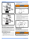
Installation in a residential garage:
1. An oil-fired furnace for installation in a residential garage must be
installed so the burner(s) and the ignition source are located not
less than 18 inches (46 cm) above the floor, and the furnace must
be located or protected to avoid physical damage by vehicles.
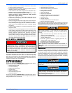
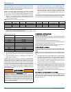
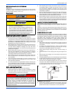
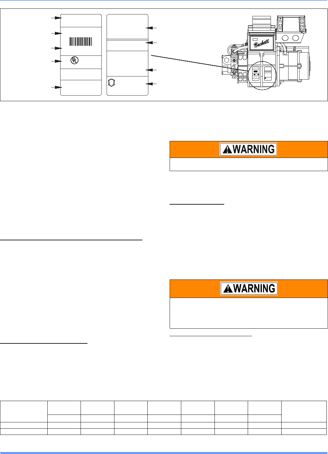
FIGURE 1: Label Location
#1or#2fueloil
MP1192BJB3001R00
ApprovalJuly1,1988
ForusewithGroup1or2
primarysaftycontrols&
MadeintheU.S.A.
ApprovalJuly1,1988
Approval#BEC-88-01
StateFireMarshall
Comm.ofMass.-
CS
DEPT.
OFFICEOF
MARSHAL
FIRE
THESTATE
P
U
B
L
I
Y
T
F
A
E
AcceptedN.Y.C.MEA.213-83-E
Elyria,Ohio
000405-62736
SERIALNUMBER
R.W.BeckettCorp.
OILBURNERNO.PI-100001
LISTED
R
R
0.50-3.00GPH,120V/60HZ5.8A
2-3/4U
100PSI
1.0X80BDLVN
0.75-1.35GPH
F3
NOZZLE:
STCPLT:
HEAD:
BJB3001R00
FIRINGRNG:
PUMPPRS:
4ULTESTSPEC
5ULTESTSPEC
6ULTESTSPEC
7ULTESTSPEC
8ULTESTSPEC
9ULTESTSPEC
000405-62736
SeriesOilBurner
Model"AF"
AF65XNATC:
MFR'SSETTINGS
RWB
ELYRIA
OHIO U.S.A.
AcceptedN.Y.C.MEA.213-83-E
Comm.ofMass.-
StateFireMarshall
Approval#BEC-88-01
ApprovalJuly1,1988
FIRE
MARSHAL
E
DEPT.
CS
A
F
I
L
T
Y
U
P
THESTATE
OFFICEOF
B
020923-49038
026-37357-000
NOZZLE: 0.65X70ADLVNHLW
EVC201 R00
PUMPPRS: 100PSI
MFR'S SETTINGS
HEAD:
STCPLT:
FIRINGRNG:
ATC:
0.5-1.10GPH
F3
3-3/8U
AF36YHHS
R.W.BeckettCorp.
OILBURNER NO.PI-100001
Series OilBurner
MadeintheU.S.A.
primarysafetycontrols&
ForusewithGroup1or2
#1or#2fueloil
MP1192 EVC201 R00
Elyria,Ohio
LISTED
R
120V/60Hz5.8A
FiringRng:0.50-0.75GPH
020923-49038
SERIALNUMBER
Model "AFEVC"
R. W. Beckett
Manufacturer’s Settings
R. W. Beckett Specification
Number and Revision
Can be Customized by
Individual Specification
State and LocalApprovals
General Model
Information
Serial Number,
Including Date Code
Rating Information
Approval Agency
Symbols
Primary Group
and Fuel Oil
Installation in an ambient below 32ºF (0.0° C) could create a haz-
ard, resulting in damage, injury or death.
Check the rating plate and power supply to be sure that the electri-
cal characteristics match. All models use nominal 115 VAC, 1
Phase 60Hz power supply.
Furnace shall be installed so the electrical components are pro-
tected from water.
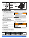
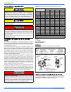
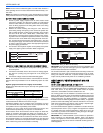
TABLE 1:
Unit Clearances to Combustibles
APPLICATION
TOP FRONT BACK SIDES
AIR INLET
PIPING
ROOF JACK
DUCT
1
1. Approved Duct Connector must be used. Refer to Section II - Ductwork.
FLOOR/BOTTOM
In. (cm) In. (cm) In. (cm) In. (cm) In. (cm) In. (cm) In. (cm)
CLOSET 2 (5.08) 6 (15.24) 0 (0.0) 0 (0.0) 0 (0.0) 3 (7.62) 0 (0.0) 0 (0.0)
ALCOVE 2 (5.08) 24 (60.96) 0 (0.0) 0 (0.0) 0 (0.0) 3 (7.62) 0 (0.0) 0 (0.0)