107272-UIM-B-1105
6 Unitary Products Group
Use the example below to help you in calculating the duct area to deter-
mine whether the ducts have sufficient area so that the furnace oper-
ates at the specified external static pressure and within the air
temperature rise specified on the nameplate.
Example: The furnace input is 80,000 BTUH, (23.4 kW) 1,200 CFM
(34.0 m
3
). The recommended duct area is 280 inch
2
(1, there are two 8
in x 14 in (20.3 cm x 35.6 cm) rectangular ducts attached to the plenum
and there are two 7 inch (722 cm
2
) round ducts attached to the furnace.
1. Take 8 in x 14 in (20.3 cm x 35.6 cm), which equals 112 inch
2
X 2
(35.6 cm x 2), which equals 224 inch
2
(1445 cm
2
) then go to round
duct size located in Table 3.
2. The square inch area for 7 inch (17.8 cm) round pipe is 38.4, mul-
tiply by 2 for two round ducts which equals 76.8 inch
2
(495 cm
2
).
3. Then take the 224 inch
2
(1445 cm
2
) from the rectangular duct and
add it to the 76.8 inch
2
(495 cm
2
) of round duct. The total square
inch of duct attached to the furnace plenum is 300.8 inch
2
(1,940
cm
2
). This exceeds the recommended 280 inch
2
(1,806 cm
2
) of
duct.
In this example, the duct system attached to the plenum has a sufficient
area so that the furnace operates at the specified external static pres-
sure and within the air temperature rise specified on the nameplate.
1. The Air Temperature Rise is determined by subtracting the Return
Air Temperature Reading from the Supply Air Temperature Read-
ing.
2. The External Static Pressure is determined by the Supply Duct
Static Pressure reading.
TABLES 2 and 3 are to be used as a guide only to help the installer
determine if the duct sizes are large enough to obtain the proper air flow
(CFM) through the furnace. TABLES 2 and 3 ARE NOT to be used to
design ductwork for the building where the furnace is being installed.
There are several variables associated with proper duct sizing that are
not included in the tables. To properly design the ductwork for the build-
ing, Refer to the ASHRAE Fundamentals Handbook, Chapter on
“DUCT DESIGN” or a company that specializes in Residential and Mod-
ular Home duct designs.
DUCKWORK INSTALLATION
Air Distribution Systems
For proper air distribution, the supply duct system shall be designed so
that the static pressure does not exceed the listed static pressure rating
on the furnace rating plate.
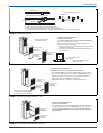
Three typical distribution systems are illustrated in Figure 3.
Location, size and number of registers should be selected on the basis
of best air distribution and floor plan of the home.
The Air Temperature Rise is to be adjusted to obtain a temperature rise
within the range(s) specified on the furnace rating plate.
DUCT DESIGN - CANADA
Supply duct design shall be in accordance with the latest HRA Digest,
the ASHRAE Handbook Fundamentals, or other good engineering prin-
ciples.
NOTE: Refer to HRA Digest Residential Air System Design Manual,
Sections 5 and 6, the requirements of which are summarized as fol-
lows:
1. The kilowatt output of each duct register shall not exceed 2.35 kW.
2. The furnace output should not be more than 20% greater than the
calculated heat loss of the home. If a larger furnace is used, the
duct system shall be capable of the increased air volumes neces-
sary to maintain a maximum air temperature rise of 50
o
C as the
air passes over the furnace heat exchanger.
3. At least one warm air supply outlet shall be provided in each room.
4. When rooms are located adjacent to the exterior walls, warm air
outlets shall be located so as to bathe at least one exterior wall
and, where practical, a window area with warm air, except for bath-
rooms or kitchens where this might not be practical.
5. Where practical, outlets shall be provided near the exterior doors
of the home.
CLEARANCE REQUIREMENTS - CANADA
Supply air ducts from warm air furnaces having a specified minimum
plenum clearance shall maintain this clearance from combustible mate-
rial for at least the distance specified in CSA Standards CAN/CSA
B139, B14.0, B140.10.
TABLE 2:
Minimum Duct Sizing For Proper Airflow
Input Airflow
Return
1
Rectangular
2
Round
2
Supply
3
Rectangular
2
Round
2
BTU/H (kW) CFM(m³) In² (cm²) in. x in.(cm x cm) in. (cm) dia In² (cm²) in. x in. (cm x cm) in. (cm) dia.
66000 (19.34) 1,050 (29.73) 280 (711) 14 x 20 (35.6 x 50.8) 18(45.7) 216(549) 12 x 18 (30.5 x 45.7) 16 (40.6)
84000 (24.62) 1,250 (35.40) 360 (914) 18 x 20 (45.7 x 50.8) 22(55.8) 280(711) 14 x 20 (35.6 x 50.8) 18 (45.7)
NOTE: This chart does not replace proper duct sizing calculations or take into account static pressure drop for run length and fittings. Watch out for the temperature rise
and static pressures.
1. Maximum return air velocity in rigid duct @ 700 feet per minute (19.82 m
3
/ minute).
2. Example return main trunk duct minimum dimensions.
3. Maximum supply air velocity in rigid duct @ 900 feet per minute (25.49 m
3
/ minute).
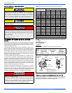
TABLE 3:
Round Duct Size
Round Duct Size Calculated Area For Each Round Duct Size
Inches (cm)
Sq. Inch (cm
2
)
5 (13) 19.8 (126)
6 (15) 28.2 (182)
7 (18) 38.4 (248)
8 (20) 50.2 (324)
9 (23) 63.6 (410)
10 (25) 78.5 (506)
11 (28) 95.0 (613)
12 (30) 113.1 (730)
13 (33) 132.7 (856)
14 (36) 153.9 (993)
The supply air temperature MUST NEVER exceed the Maximum
Supply Air Temperature, specified on the nameplate.
Operating the furnace above the maximum supply air temperature
will cause the heat exchanger to overheat, causing premature heat
exchanger failure. Improper duct sizing, dirty air filters, incorrect oil
pump pressure, incorrect oil orifice and/or a faulty limit switch can
cause the furnace to operate above the maximum supply air tem-
perature. Refer to SECTIONS II, III and VIII for additional informa-
tion on correcting the problem.


