


107272-UIM-B-1105
Unitary Products Group 13
Follow information provided with the burner, the fuel pump, or the calcu-
lation below to determine pipe size and length.
L = Line Length in feet
H = Head in feet
Q = Firing rate in GPH
3/8” (0.95 cm) line L = (6 - 0.75 x H) / 0.0086 x Q)
1/2” (1.27 cm) line L = (6 - 0.75 x H) / (0.00218 x Q)
If tank is above the oil pump, then use the following calculation:
3/8” (0.95 cm) line L = (6 + 0.75 x H) / (0.0086 x Q)
1/2” (1.27 cm) line L = (6 + 0.75 x H) / (0.00218 x Q)
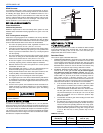
IMPORTANT: The recommended piping configuration is a single or two
pipe system that is inserted into the top of the tank as shown in Figure
17 or 18. The two pipe system should be used in applications where the
oil tank is considerably lower than the burner and the oil pump keeps
losing its prime. The oil line should never be connected to the bottom of
the oil tank if the oil tank is outdoors. Water in the bottom of the oil will
freeze in the winter causing the oil line to freeze.
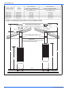
ONE PIPE SYSTEM
DO NOT INSTALL BY-PASS PLUG! Connect inlet line to pump inlet.
Start burner. Arrange primary burner control for continuous operation
during the purging. Place a clear plastic tube on bleed valve. Open
bleed valve 1 turn counterclock wise. Bleed until all air bubbles disap-
pear. Tighten bleed valve securely. Hurried bleeding will impair efficient
operation of unit. Refer to Figures 16 and 17.
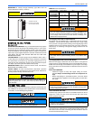
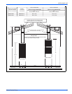
TWO PIPE SYSTEM
Remove 1/16” (0.16 cm) pipe by-pass plug from plastic bag attached to
the unit. Remove 1/4” (0.635 cm) plug from return port. Insert by-pass
plug into the return port of the oil pump. The oil pump return port loca-
tion is shown in Figure 16.
Insert a 1/4” MPT x flare adaptor into the by-pass port and the inlet port.
Attach the return and inlet copper lines that go to the oil tank. Start the
burner. DO NOT open the bleed valve. The air in the oil lines will bleed
automatically.
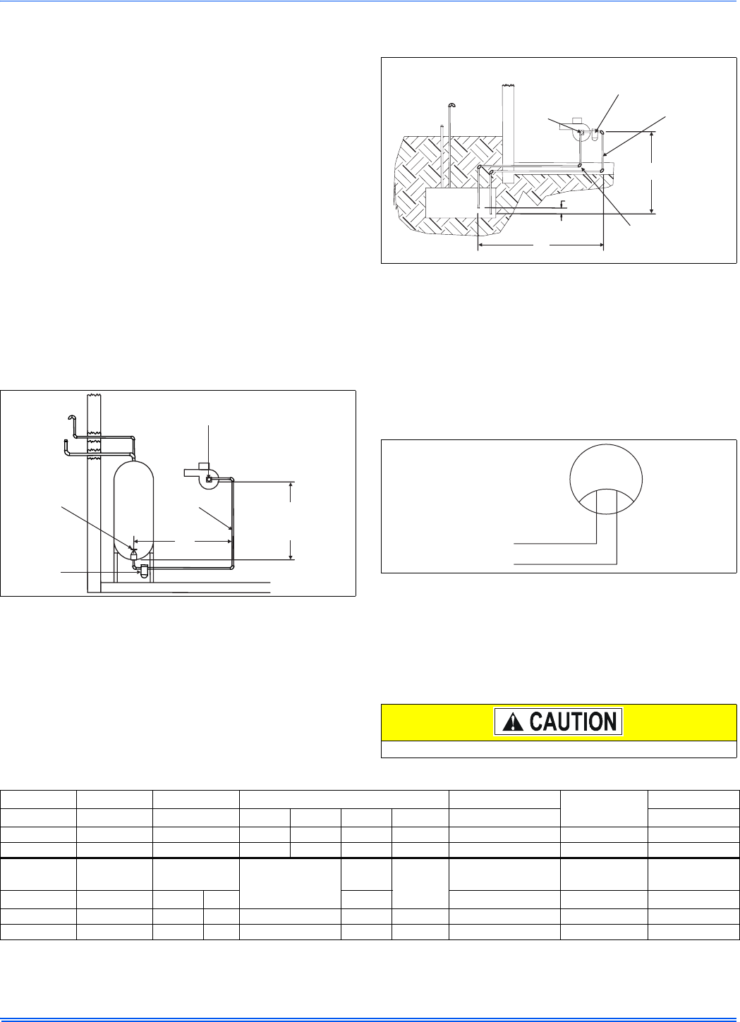
The return line must terminate 3” to 4” above supply line in the oil tank.
Failure to do this may introduce air into the system and could result in
the loss of the prime. Refer to Figure 18.
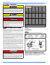
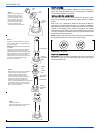
SOLENOID WIRING
DISCONNECT THE POWER SUPPLY BEFORE WIRING TO PRE-
VENT ELECTRICAL SHOCK OR EQUIPMENT DAMAGE.
Lead wires on these devices are long enough to reach the junction box
on most burner installations. Refer to Figure 19.
NOTE: Check the burner manufacturer’s installation sheets for the cor-
rect solenoid wiring. All electrical wiring must be done in accordance
with the local codes.
NOTE: Solenoid power requirements: 115 VAC, 0.1 Amp, 60 Hz
SECTION V: ELECTRICAL POWER
Electrical Power Connections
Field wiring to the unit must be grounded. Electric wires that are field
installed shall conform to the temperature limitation for 63°F (35°C) rise
wire when installed in accordance with instructions. Refer to Table 8 in
these instructions for specific furnace electrical data.
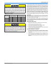
Annual Fuel Utilization Efficiency (AFUE) numbers are determined in accordance with DOE Test procedures.
Wire size and over current protection must comply with the National Electrical Code (NFPA-70-latest edition) and all local codes.
The furnace shall be installed so that the electrical components are protected from water.
Rotation when facing shaft end.
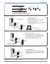
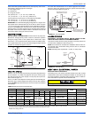
FIGURE 17: One-Pipe System
Oil
Tank
Maximum
One Pipe (H)
Lift: 8 Ft
“R”
Inlet
Fuel Unit
Primary
Filter
Shut-Off
Valve
Fill
Pipe
Air
Vent
L=H+R
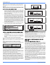
FIGURE 18: Two-Pipe System
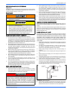
FIGURE 19: Solenoid Wiring
Use copper conductors only.
Oil
Tank
Fill
Pipe
Air
Vent
Outside Tank Fuel Unit
Above Bottom of Tank
Fuel
Unit
Inlet
Primary
Filter
L=H+R
“R”
“H”
Use Protective Plastic
Tubing in Concrete or as
Local Codes Require
3”-4”
To Power
Control
Violet
White
Bypass
Solenoid
Valve
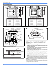
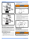
TABLE 8: Ratings & Physical / Electrical Data
Input Output Nominal Burner Air Temp. Rise
AFUE
Input Rate
MBH (kW) MBH (kW) CFM (cm) Amps HP RPM Rotation °F (°C) GPH (Liter / H)
66 (19.3) 53 (15.5) 1050 (29.7) 2.1 1/7 3450 CCW 45 - 75 (28 - 47) 80 0.50 (1.9)
84 (24.6) 67 (19.6) 1250 (35.4) 2.1 1/7 3450 CCW 45 - 75 (28 - 47) 80 0.65 (2.5)
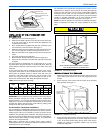
Input
Max. Outlet
Air Temp
Blower
Max Over-current
Size (awg) @
75 ft. protect
Total
Unit
Min. Wire
One Way
Blower Size
DFAA
Operation Wgt.
DFAH
Operation Wgt.
MBH (kW) °F (°C) Hp Amps Amps In. (cm) LBS/Kg LBS/Kg
66 (19.3) 165 (74) 1/6 8.0 15 8.3 14 10 x 8 (25.4 x 20.3) 175/79.4 158/71.7
84 (24.6) 165 (74) 1/4 5.9 15 7.8 14 10 x 8 (25.4 x 20.3) 175/79.4 158/71.7