


036-21216-003-A-0204
Unitary Products Group 13
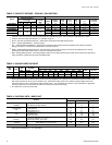
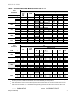
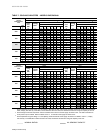
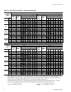
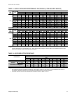
TABLE 11: SUPPLY AIR BLOWER PERFORMANCE DHE/DHG060
1
(5 TON GAS HEAT MODELS)
UNIT
SIZE
(MBH)
AIR FLOW
CFM
AVAILABLE EXTERNAL STATIC PRESSURE - IWG
2
0.20 0.30 0.40 0.50 0.60 0.70 0.80
RPM Watts RPM Watts RPM Watts RPM Watts RPM Watts RPM Watts RPM Watts
060
2500 1059 1560 1077 1590 1095 1630 1114 1650 1134 1660 1158 1685 1181 1720
2400 1032 1405 1054 1470 1074 1525 1094 1560 1116 1595 1140 1620 1167 1640
2300 1005 1260 1024 1275 1049 1370 1069 1440 1090 1475 1116 1505 1142 1535
2200 980 1160 1002 1170 1022 1190 1044 1250 1066 1350 1090 1410 1117 1440
2100 930 1060 957 1070 983 1080 1010 1100 1039 1160 1064 1260 1092 1340
2000 877 950 908 975 941 1000 976 1020 1009 1050 1040 1100 1070 1225
1900 - - - - 894 885 940 940 980 980 1014 1020 1047 1095
1800 - - - - 855 815 903 860 950 905 988 940 1022 970
1700 - - - - - - 884 815 925 850 964 880 1001 910
1600 - - - - - - 864 770 908 805 948 835 987 870
1500 - - - - - - - - 882 740 926 780 965 830
UNIT
SIZE
(MBH)
AIR FLOW
CFM
AVAILABLE EXTERNAL STATIC PRESSURE IWG
1
0.90 1.00 1.10 1.20 1.30 1.40 1.50
RPM Watts RPM Watts RPM Watts RPM Watts RPM Watts RPM Watts RPM Watts
060
2500 - - - - - - - - - - - - - -
2400 1193 1665 - - - - - - - - - - - -
2300 1170 1580 1202 1620 - - - - - - - - - -
2200 1148 1480 1180 1530 - - - - - - - - - -
2100 1121 1385 1155 1425 1190 1475 - - - - - - - -
2000 1100 1285 1133 1340 1169 1385 1205 1445 - - - - - -
1900 1079 1180 1110 1240 1143 1280 1178 1330 1222 1375 - - - -
1800 1058 1060 1090 1135 1122 1190 1158 1240 1196 1295 - - - -
1700 1035 960 1071 1030 1103 1100 1134 1140 1164 1175 1197 1205 - -
1600 1020 900 1056 965 1088 1035 1118 1065 1145 1105 1170 1130 1198 1150
1500 1004 860 1038 880 1070 925 1101 980 1130 1045 1158 1075 1184 1110
1.
Models shown at 230/460 Volts with side duct connections.
2.
Includes allowances for a wet evaporator coil, 1” filters and the heat exchangers. Refer to Table 12 for resistance values on appli-
cations other than gas / electric units with side duct airflows.
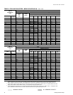
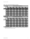
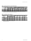
TABLE 12: ACCESSORY STATIC RESISTANCE
DESCRIPTION
EXTERNAL STATIC PRESSURE DROP
RESISTANCE, IWG
CFM
1000 1200 1400 1600 1800 2000 2200 2400 2600 2800 3000
ECONMIZER
1
2
0.07 0.08 0.09 0.11 0.13 0.15 0.17 0.20 0.23 0.26 0.30
ELECTRIC
HEATERS
3
5-15 kW 0.04 0.05 0.06 0.07 0.08 0.10 0.12 0.14 0.16 0.19 0.22
20 - 30 kW 0.06 0.07 0.08 0.09 0.11 0.13 0.15 0.17 0.20 0.23 0.26
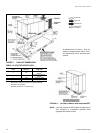
BOTTOM DUCT CONNECTIONS
1
0.06 0.07 0.08 0.09 0.10 0.11 0.12 0.14 0.16 0.19 0.22
COOLING ONLY
2
0.08 0.10 0.12 0.14 0.16 0.18 0.20 0.23 0.26 0.29 0.32
1.
Deduct these resistance values from the available external static pressure shown in Tables 10 and 11.
2.
The pressure through the economizer is greater for 100% outdoor air than for 100% return air. If the resistance of the return air
duct system is less than 0.25 IWG, the unit will deliver less CFM during full economizer operation.
3.
Add these resistance values to the available static resistance values on Tables 10 and 11.