


177820-YIM-A-0506
6 Unitary Products Group
LOCATION
Use the following guidelines to select a suitable loca-
tion for these units.
1. Unit is designed for outdoor installation only.
2. Condenser coils must have an unlimited supply of
air.
3. Where a choice of location is possible, position the
unit on either north or east side of building.
4. For ground level installation, use a level concrete
slab with a minimum thickness of 4 inches. The
length and width should be at least 6 inches
greater than the unit base rails. Do not tie slab to
the building foundation.
5. Roof structures must be able to support the weight
of the unit and its options and/or accessories. Unit
must be installed on a solid level roof curb or
appropriate angle iron frame.
6. Maintain level tolerance to 1/2 inch maximum
across the entire length or width of the unit.
If a unit is to be installed on a roof curb or special frame
other than a YORK roof curb, gasketing must be
applied to all surfaces that come in contact with the unit
underside.
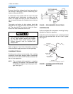
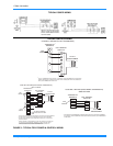
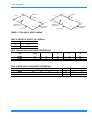
RIGGING AND HANDLING
Exercise care when moving the unit. Do not remove
any packaging until the unit is near the place of installa-
tion. Rig the unit by attaching chain or cable slings to
the lifting holes provided in the base rails. Spreader
bars, whose length exceeds the largest dimension
across the unit, MUST BE USED.
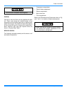
Units may also be moved or lifted with a forklift. Slotted
openings in the base rails are provided for this pur-
pose. Fork lengths must be a minimum of 42 inches.
Remove the nesting brackets from the four corners on
the top of the unit. All screws that are removed when
removing the brackets must be replaced on the unit.
Refer to Table 8 for unit weights and to the Figure 6 for
approximate center of gravity.
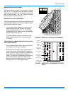
CLEARANCES
All units require certain clearances for proper operation
and service. Installer must make provisions for ade-
quate ventilation air. Refer to Dimensions and Clear-
ances shown in Figures 7 through 10 and Table 14 for
the clearances required for combustible construction,
servicing, and proper unit operation.
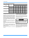
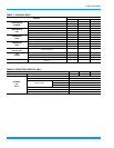
TABLE 1: UNIT APPLICATION DATA (BCH)
UNIT MODEL NUMBER 036 048 060
Voltage Variation,
Min. / Max.
1
208/230 187 / 253
460 414 / 506
575 518 / 630
Supply Air CFM, Nom. 1200 1600 2000
Wet Bulb Temperature (ºF) of Air on
Evaporator Coil, Min. / Max
57 / 72
Dry Bulb Temperature (ºF) of Air on
Condenser Coil, Min. / Max.
0 / 120
1.
Utilization range “A” in accordance with ARI Standard 110.
Before lifting a unit, make sure that all panels
are in place and that its weight is distributed
equally on all cables so it will lift evenly.
Do not permit overhanging structures or shrubs
to obstruct outdoor air discharge outlet, com-
bustion air inlet or vent outlets.