


177820-YIM-A-0506
34 Unitary Products Group
of the UCB. If 24 volts is present, trace the wiring
from Y1 “OUT” for incorrect wiring. If 24 volts is not
present at the Y1 “OUT” terminal, the UCB must be
replaced.
12. For units without economizers: If 24 volts is present
at the Y1 OUT terminal, check for 24 volts at the
Y1 “ECON” terminal. If 24 volts is not present,
check for loose wiring from the Y1 “OUT” terminal
to the Mate-N-Lock plug, the jumper in the Mate-N-
Lock plug, and in the wiring from the Mate-N-Lock
plug to the Y1 “ECON” terminal.
13. For units with economizers: If 24 volts is present at
the Y1 “OUT” terminal, check for 24 volts at the Y1
“ECON” terminal. If 24 volts is not present, check
for loose wiring from the Y1 “OUT” terminal to the
Mate-N-Lock plug, a poor connection between the
UCB and economizer Mate-N-Lock plugs, loose
wiring from the Mate-N-Lock plug to the econo-
mizer, back to the Mate-N-Lock plug, and from the
Mate-N-Lock plug to the Y1 “ECON” terminal. If
nothing is found, the economizer actuator may
have faulted and is failing to return the 24-volt “call”
to the Y1 “ECON” terminal even though the econo-
mizer is not providing free cooling. To test, discon-
nect the Mate-N-Locks and jumper between the
WHITE and YELLOW wires of the UCB’s Mate-N-
Lock plug. If the compressor energizes, there is a
fault in the economizer wiring or actuator.
14. The UCB can be programmed to lock out compres-
sor operation during free cooling and in low ambi-
ent conditions. These options are not enabled by
default. Local distributors can test the UCB for this
programming.
For units with factory installed economizers, the
UCB is programmed to lock out compressor opera-
tion when the LAS set point is reached.
For units without factory installed or with field
installed economizers, the UCB allows compressor
operation all the time. This programming can be
checked or changed by the local distributor.
15. If none of the above correct the error, replace the
UCB.
UNIT FLASH CODES
Various flash codes are utilized by the unit control
board (UCB) to aid in troubleshooting. Flash codes are
distinguished by the short on and off cycle used
(approximately 200ms on and 200ms off). To show
normal operation, the control board flashes a 1 second
on, 1 second off “heartbeat” during normal operation.
This is to verify that the UCB is functioning correctly.
Do not confuse this with an error flash code. To prevent
confusion, a 1-flash, flash code is not used.
Current alarms are flashed on the UCB LED. Pressing
and releasing the ALARMS button on the UCB can
check the alarm history. The UCB will cycle through the
last five (5) alarms, most recent to oldest, separating
each alarm flash code by approximately 2 seconds.
In some cases, it may be necessary to “zero” the
ASCD for the compressors in order to perform trouble-
shooting. To reset all ASCDs for one cycle, press and
release the UCB TEST button once.
MAINTENANCE
NORMAL MAINTENANCE
FILTERS
Inspect once a month. Replace disposable or clean
permanent type as necessary. DO NOT replace per-
manent type with disposable. The dimensional size of
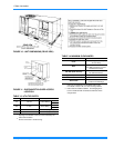
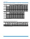
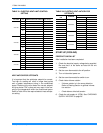
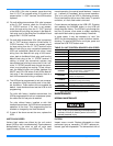
TABLE 23: UNIT CONTROL BOARD FLASH CODES
Flash Code Description
On Steady
Control Failure - Replace Control
Heart Beat
Normal Operation
1 Flash
Not Applicable
2 Flashes
Control waiting ASCD
1
1.
These flash codes do not represent alarms.
3 Flashes
HPS1 - Compressor Lock out
5 Flashes
LPS1 - Compressor Lock out
7 Flashes
FS1 - Compressor Lock out
9 Flashes
Ignition Control Locked Out/
Ignition Control Failure / Limit Switch Trip /
No Jumper Plug in Heat Section
10 Flashes
Compressors Locked Out On Low
Outdoor Air Temperature
1
11 Flashes
Compressors Locked Out Because the
Economizer Is Using Free Cooling
1
13 Flashes
Compressor Held Off Due To Low Voltage
1
14 Flashes
EEPROM Storage Failure (Control Failure)
OFF
No Power or Control Failure
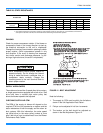
Prior to any of the following maintenance pro-
cedures, shut off all electric power to the unit to
prevent personal injury.