


177820-YIM-A-0506
Unitary Products Group 27
Start the supply air blower motor. Adjust the resis-
tances in both the supply and the return air duct sys-
tems to balance the air distribution throughout the
conditioned space. The job specifications may require
that this balancing be done by someone other than the
equipment installer.
To check the supply air CFM after the initial balancing
has been completed:
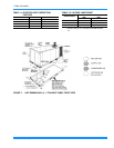
1. Remove the two 5/16” dot plugs from the blower
motor and the filter access panels shown in Figure
11.
2. Insert at least 8" of 1/4 inch tubing into each of
these holes for sufficient penetration into the air
flow on both sides of the indoor coil.
NOTE: The tubes must be inserted and held in a posi-
tion perpendicular to the air flow so that veloc-
ity pressure will not affect the static pressure
readings.
3. Using an inclined manometer, determine the pres-
sure drop across a dry evaporator coil. Since the
moisture on an evaporator coil may vary greatly,
measuring the pressure drop across a wet coil
under field conditions would be inaccurate. To
assure a dry coil, the compressors should be deac-
tivated while the test is being run.
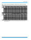
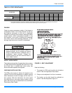
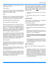
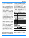
4. Knowing the pressure drop across a dry coil, the
actual CFM through the unit can be determined
from the curve in Pressure Drop vs. Supply Air
CFM (Figure 13).
After readings have been obtained, remove the tubes
and reinstall the two 5/16” dot plugs that were removed
in Step 1.
NOTE: De-energize the compressors before taking
any test measurements to assure a dry indoor
coil.
OPERATION
SEQUENCE OF OPERATIONS OVERVIEW
For these units, the thermostat makes a circuit
between “R” and “Y1” for the cooling cycle.
The call is passed to the unit control board (UCB),
which then determines whether the requested opera-
tion is available and, if so, which components to ener-
gize.
For heating, the thermostat makes a circuit between
“R” and “W1”. The UCB energizes the compressor and
condenser fan allowing the unit to run in heating mode.
A time / temperature control operates the defrost cycle.
If at any time a call for both heating and cooling are
present, the heating operation will be performed. If
operating, the cooling system is halted as with a com-
pletion of a call for cooling. Heating always takes prior-
ity.
COOLING SEQUENCE OF OPERATION
CONTINUOUS BLOWER
By setting the room thermostat fan switch to “ON,” the
supply air blower will operate continuously.
Failure to properly adjust the total system air
quantity and static pressure can result in
extensive system damage.
FIGURE 13 - PRESSURE DROP ACROSS COIL
0
0.1
0.2
0.3
0.4
0.5
1000 1500 2000 2500 3000
036
048
060
NOMINAL CFM
PRESSUREDROP (IWG)