


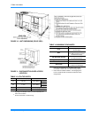


177820-YIM-A-0506
Unitary Products Group 31
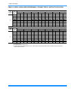
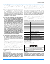
HEAT ANTICIPATOR SETPOINTS
It is important that the anticipator setpoint be correct.
Too high of a setting will result in longer heat cycles
and a greater temperature swing in the conditioned
space. Reducing the value below the correct setpoint
will give shorter “ON” cycles and may result in the low-
ering of the temperature within the conditioned space.
Refer to Table 22 for the required electric heat anticipa-
tor setting.
START-UP (COOLING)
PRESTART CHECK LIST
After installation has been completed:
1. Check the electrical supply voltage being supplied.
Be sure that it is the same as listed on the unit
nameplate.
2. Set the room thermostat to the off position.
3. Turn unit electrical power on.
4. Set the room thermostat fan switch to on.
5. Check indoor blower rotation.
• If blower rotation is in the wrong direction.
Refer to Phasing Section in general informa-
tion section.
• Check blower drive belt tension.
6. Check the unit supply air (CFM). See “CHECKING
SUPPLY AIR CFM” on page 26.
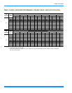
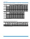
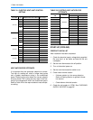
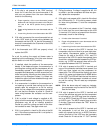
TABLE 21: ELECTRIC HEAT LIMIT CONTROL
SETTING
VOLTAGE kW TEMPERATURE LIMIT SWITCH
Open Temp
º
F
5 1 140
7 1,3 140
10 1,2,3 140
15 2,4,6 140
1,2,3,4,5 140
6 150
30 1,2,3,4,5,6 150
5 1,2,3 140
7 1,2,3 140
10 1,2,3 150
15 2,4,6 140
20 1,2,3,4,5,6 150
1,3,5 160
2,4,6 150
7 2,4,6 140
10 2,4,6 140
15 2,4,6 140
20 3 160
30 3 150
10 2,4,6 140
15 2,4,6 140
20 5 160
30 5 150
20
30
230-3-60
460-3-60
575-3-60
230-1-60
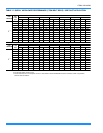
TABLE 22: ELECTRIC HEAT ANTICIPATOR
SETPOINTS
HEATER
KW
VOLTAGE
SETTING, AMPS
TH1 TH2
5
230-3-60
0.024 0.35
7 0.024 0.35
10 0.024 0.35
15 0.024 0.35
20 0.024 0.35
30 0.024 0.35
7
460-3-60
0.024 0.35
10 0.024 0.35
15 0.024 0.35
20 0.024 0.37
30 0.024 0.37
10
575-3-60
0.024 0.35
15 0.024 0.35
20 0.024 0.37
30 0.024 0.37