


177820-YIM-A-0506
30 Unitary Products Group
The ASCD is initiated on unit start-up and on any com-
pressor reset or lock-out.
FLASH CODES
The UCB will initiate a flash code associated with
errors within the system. Refer to UNIT CONTROL
BOARD FLASH CODES Table 23.
RESET
Remove the call for cooling, by raising thermostat set-
ting higher than the conditioned space temperature.
This resets any pressure or freezestat flash codes.
HEATING SEQUENCE OF OPERATIONS
WITH OR WITHOUT ELECTRIC HEAT
When the thermostat calls for the first stage of heating,
the low voltage control circuit is completed between “R”
and “W1”. The 24vac signal is passed through the
UCB to the “Y” contact on the Defrost Control (DC)
assuring the reversing valve cannot be energized,
except during defrost. If the ASCD timer is satisfied the
UCB will energize compressor contactor M1.
If the compressor alone cannot satisfy the heating
requirements, a second stage call from the thermostat
completes the circuit between “R” and “W2”. This
24vac signal is passed through the UCB to the electric
heat section (if available). The total available kW of
electric heat will be energized on a call for “W2”.
DEFROST MODE
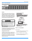
As mentioned earlier, the defrost control (DC) utilizes a
time/temperature defrost scheme. The following two
conditions must be met before the DC will enter a
defrost mode:
The defrost thermostat (SD) must be closed. This nor-
mally open thermostat is mounted on the liquid line and
is set to close at 28 ± 4°F.
Once the defrost thermostat closes, the defrost control
starts a run timer that must be satisfied before defrost
can begin. This is accumulated compressor run time.
The selection pin is factory set at 60 minutes, but is
field adjustable to 30, 60 or 90 minutes.
When the DC enters the defrost mode, it’s on-board
defrost relay is powered. This energizes the reversing
valve, de-energizes the condenser fan motor and ener-
gizes the unit’s optional electric heater. The DC
remains in defrost mode until either
of the following two
conditions is met:
1. The liquid line thermostat is open. It is set to open
at 55 ± 4°F.
2. The maximum defrost run time of 10 minutes is
met.
FORCED DEFROST
The processor on the defrost board is only energized
when the defrost sensor (DS) is closed.
To create a forced defrost:
1. The DS must either be closed or a jumper must be
placed across the DFS terminals on the board.
2. Place a jumper across the test pin terminals on the
board.
Depending on the selected defrost minimum run
time of 30, 60 or 90 minutes, the board will go into
defrost in 7.5, 15 or 22.5 seconds.
The DC will remain in defrost until the jumpers
across the DS and the test pin terminals are
removed.
Once the jumpers are removed, the board then ter-
minates defrost when the DS opens or a maximum
of 10 minutes after the test pin jumper is removed,
whichever comes first.
SAFETY CONTROLS
The control circuit includes the following safety con-
trols:
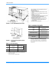
1. Temperature Limit Switch (TLS) - This control is
located inside the heater compartment and is set to
open at the temperature indicated in the Electric
Heat Limit Control Setting Table 21. It resets auto-
matically. The limit switch operates when a high
temperature condition, caused by inadequate sup-
ply air flow occurs, thus shutting down the heater
and energizing the blower.