


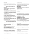
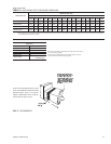

CLEARANCES
All units require certain clearances for proper operation and
service. Refer to Figure 3 for the clearances required for com
-
bustion, construction, servicing and proper unit operation.
WARNING:Do not permit overhanging structures or shrubs to
obstruct the condenser air discharge outlet.
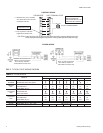
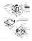
DUCT WORK
These units are adaptable to downflow use as well as rear
supply and return air duct openings. To convert to downflow,
use the following steps:
1. Remove the duct covers found in the bottom return and
supply air duct openings. There are four (4) screws secur
-
ing each duct cover (save these screws to use later).
2. Install theductcovers, removedin stepone, totherear sup
-
ply and return air duct openings. Secure with the four (4)
screws used in step one.
3. Seal duct covers with silicone caulk.
Downflow units must have an “L”-shaped supply duct without
any outlets or registers located below the outlet of the unit.
Duct work should be designed and sized according to the
methods of the Air Conditioning Contractors of America
(ACCA), as set forth in their Manual D.
A closed return duct system shall be used. This shall not pre-
clude use of economizers or ventilation air intake. Flexible
joints may be used in the supply and return duct work to mini-
mize the transmission of noise.
CAUTION: When fastening duct work to the side duct flanges on
the unit,insert thescrews through theduct flangesonly.
DO NOTinsert the screwsthrough thecasing. Outdoor
duct work must be insulated and waterproofed.
NOTE: Be sure to note supply and return openings.
Refer to Figure 4 for information concerning rear and bottom
supply and return air duct openings.
FILTERS
Single phase units are shipped without a filter and is the re
-
sponsibility of the installer to secure a filter in the return air
ductwork or install a Filter/Frame Kit (1FF0114).
A filter rack and a high velocity filters are standard on three
phase units.
Filters must always be used and must be kept clean. When
filters become dirt laden, insufficient air is delivered by the
blower, decreasing your unit's efficiency and increasing oper
-
ating costs and wear-and-tear on the unit and controls.
Filters should be checked monthly especially since this unit is
used for both heating and cooling.
CONDENSATE DRAIN
A condensate trap is required to be installed in the conden
-
sate drain. The plumbing must conform to local codes. Use a
sealing compound on male pipe threads. Install the conden
-
sate drain line (
" NPTF) to spill into an open drain.
SERVICE ACCESS
Accessto allserviceable componentsisprovided bythe follow
-
ing removable panels:
•
Blower service access
•
Electrical/Filter access
•
Compressor service access
Refer to Figure 3 for location of these access panels and mini
-
mum clearances.
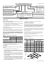
THERMOSTAT
The room thermostat should be located on an inside wall ap
-
proximately 56" above the floor where it will not be subject to
drafts, sun exposure or heat from electrical fixtures or appli
-
ances. Follow manufacturer's instructions enclosed with the
thermostat for general installation procedure. Six color coded
insulated wires (minimum #18 AWG) should be used to con
-
nect thermostat to unit. See Figure 2.
POWER AND CONTROL WIRING
Field wiring to the unit must conform to provisions of the cur-
rent N.E.C. ANSI/NFPA No. 70 or C.E.C. and/or local ordi-
nances. The unit must be electrically grounded in
accordance with local codes or, in their absence, with the
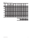
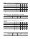
N.E.C./C.E.C. Voltage tolerances which must be maintained
at the compressor terminals during starting and running con-
ditions are indicated on the unit Rating Plate and Table 3.
The wiring entering the cabinet must be provided with me
-
chanical strain relief.
Afused disconnect switch should be field provided for the unit. If
any of the wire supplied with the unit must be replaced, replace
-
ment wire must be of the type shown on the wiring diagram.
Electrical line must be sized properly to carry the load. Each
unit must be wired with a separate branch circuit fed directly
from the meter panel and properly fused.
Refer to Figure 2 for typical fieldwiring and to the appropriate unit
wiring diagram for control circuit and powerwiring information.
COMPRESSORS
Units are shipped with compressor mountings factory-
adjusted and ready for operation.
CAUTION: Do Not loosen compressor mounting bolts.
66297-YIM-C-0205
Unitary Products Group 3