


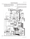
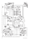

gized. Poweris suppliedto thecompressor andoutdoor fan
motor, and the reversingvalve switched tothe cooling posi
-
tion.When thefan switchonthe thermostatis inthe“AUTO”
position the indoor blower motor is energizedat the cooling
airflow.
3. When the demand for cooling has been satisfied, the 24
volt “Y” signal is removed, and the M1 contactor is de-
energized. When the fan switch on the thermostat is in the
“ON” position, the indoor blower motor continues to run. If
the fan switch is in the “AUTO” position. the indoor motor
ramps down over a 30-second period.
HEATING OPERATION (B1HH060 with ECM indoor motor)
1. When the fan switch on the thermostat is in the “ON” posi
-
tion, the 24 voltsat “G” brings on the indoor blowermotor at
the heatingflow. Whenthefan switchon thethermostat isin
the “AUTO” position, the blower operates when there is a
call for heating by the thermostat.
2. On acall forheating, thethermostatsends 24volts to“Y” on
the fan control board. After the anti-short cycle period is
complete, the 24 volt signal energizes contactor coil M1
and power is supplied to the compressor and outdoor fan
motor. The reversing valve remains in the heating position.
When the fan switch onthe thermostat is in the “AUTO” po
-
sition,the indoorblower isenergizedat theheatingairflow.
3. For units equipped with supplementary electric heat, when
the heat pump cannot meet the demand, the thermostat
“W” sends 24 volts to “W2” on the fan control board. This
signal also is sent throughthe defrost control terminals “W”
and “W6” and back to the fan control “W1”. The 24 volt sig
-
nal energizes all stages of electric heat.
4 When the heating demand is satisfied, the electric heat is
de-energized when the 24 volt “W” signal is removed, and
the M1 contactor is de-energized when the 24 volt “Y” sig
-
nal is removed. When the fan switch on thethermostat is in
the“ON” position,the indoorblowercontinues torun. When
the fan switch is in the “AUTO” position, the indoor blower
motor ramps down over a 15-second period.
Please refer to Tables 22 and 23 for more information.
16 Unitary Products Group
66297-YIM-C-0205
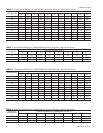
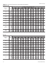
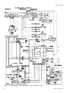
SIGNAL STATE BOARD FUNCTION
“G”
ON FAN INSTANT ON
OFF FAN INSTANT OFF
“G” & “Y” & “O”
ON
FAN INSTANT ON
COMPRESSOR AND OUTDOOR FAN INSTANT ON (AFTER ANTI-SHORT CYCLE DELAY)
REVERSING VALVE ENERGIZED
SYSTEM OPERATES IN COOLING
OFF
COMPRESSOR AND OUTDOOR FAN INSTANT OFF
FAN 60 SEC. DELAY OFF
“G” & “Y”
ON
FAN INSTANT ON
COMPRESSOR AND OUTDOOR FAN INSTANT ON (AFTER ANTI-SHORT CYCLE DELAY)
SYSTEM OPERATES IN HEATING
OFF
COMPRESSOR AND OUTDOOR FAN INSTANT OFF
FAN 60 SEC. DELAY OFF
“G” & “W”
ON
FAN INSTANT ON
HEATER BANK 1 ELEC. HEAT INSTANT ON
HEATER BANK 2 ELEC. HEAT 10 SEC. DELAY ON
HEATER BANK 3 ELEC. HEAT 20 SEC. DELAY ON
OFF
HEATER BANK 3 ELEC. HEAT INSTANT OFF
HEATER BANK 2 ELEC. HEAT
SEC. DELAY OFF
HEATER BANK 1 ELEC. HEAT 1 SEC. DELAY OFF
FAN 10 SEC. DELAY OFF
“G” & “Y” & “W”
ON
FAN INSTANT ON
COMPRESSOR AND OUTDOOR FAN INSTANT ON
SYSTEM OPERATES IN HEATING
HEATER BANK 1 ELEC. HEAT INSTANT ON
HEATER BANK 2 ELEC. HEAT 10 SEC. DELAY ON
HEATER BANK 3 ELEC. HEAT 20 SEC. DELAY ON
OFF
COMPRESSOR AND OUTDOOR FAN INSTANT OFF
HEATER BANK 3 ELEC. HEAT INSTANT OFF
HEATER BANK 2 ELEC. HEAT
SEC. DELAY OFF
HEATER BANK 1 ELEC. HEAT 1 SEC. DELAY OFF
FAN 60 SEC. DELAY OFF
“W”
ON
FAN INSTANT ON
HEATER BANK 1 ELEC. HEAT INSTANT ON
HEATER BANK 2 ELEC. HEAT 10 SEC. DELAY ON
HEATER BANK 3 ELEC. HEAT 20 SEC. DELAY ON
OFF
HEATER BANK 3 ELEC. HEAT INSTANT OFF
HEATER BANK 2 ELEC. HEAT
SEC. DELAY OFF
HEATER BANK 1 ELEC. HEAT 1 SEC. DELAY OFF
FAN 10 SEC. DELAY OFF
TABLE 22 - THERMOSTAT SIGNALS (SINGLE PHASE UNITS)
SECURE OWNER'S APPROVAL: When the system is
functioning 1/6 properly, secure the owner's approval. Show
him the location of all disconnect switches and the thermostat.
Teach him how to start and stop the unit and how to adjust tem
-
perature settings within the limitations of the system.