


7
12 MA
94 (MAX)
82+3 (MIN)
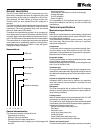
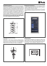
Anti-vibratory supports
Whenever a maximum reduction of vibration and noise gener-
ated by the unit is required, a set of steel spring anti-vibratory
supports can be used. These should be installed between the
supporting frame of the unit and the base or floor where same
is to be located. This base should be solid and sized in ac-
cordance with the weight to be supported. 12MA bolts are
use to secure the supports to the base of the frame. This anti-
vibratory support accessory for YLCC-42/62 includes 4
springs, whereas for YLCC-82/102/122/152 it includes 6. These
spring supports should be distributed and secured by means
of the corresponding holes drilled in the chiller base, the loca-
tion of which is detailed in General Dimensions.
Flow switch (optional accessory)
Flow switch
Switch with a 1" MPT thread, adequate for a Design Operat-
ing Pressure of 10 bar hand so as to protect the equipment
against water flow drops. This switch, or an equivalent, is
required for the site installation of each unit (obligatory).
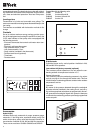
Remote control (accessory)
For access and control by means of the buttons and LEDs
available. Allows selecting the cool, heat and OFF functions,
and the red LED indicates any failure.
Can be installed at a maximum distance of 50 m. The remote
terminal should be connected to the unit with a 7 x 0,35 mm
2
cable.
Remote terminal
For total access and control of the system by means of the
display, buttons and LEDs. Allows selecting cool, heat and
off functions. Can also modify operating parameters and moni-
tor the system. Can be installed at a distance of 150 m.