


36
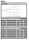
Parameter
Calibration probe B1 (entering water
temperature)
Description Unit
Calibration probe B2 (discharge water
temperature exchanger 1)
Calibration probe B3 (refrigerant
temperature circuit 1)
Calibration probe B4 (discharge water
temperature exchanger 2)
Calibration probe B5 (refrigerant
temperature circuit 2)
/6
/7
/8
/9
/A
0.1°C/F
0.1°C/F
0.1°C/F
0.1°C/F
0.1°C/F
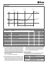
Parameter H9 Remote terminal Local terminal
0 Activated Deactivated
1 Activated Activated
2 Deactivated Deactivated
3 Deactivated Activated
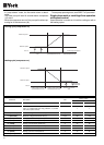
Parameter P4 Buzzer function
0 Always disconnected
Between 1 & 14
15
Disconnects once this value in minutes is over
Operating until the cause of the alarm disappears
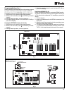
Yellow and green LEDs on base plate
The yellow LED indicates unit operation. Under normal condi-
tions, it flashes once per second. In the case of an alarm, it
flashes twice per second. When it goes off, no voltage is reach-
ing the base plate.
The green LED indicates communication with the remote ter-
minal. In the case of a communication failure, this LED re-
mains off (failures are normally due to bad contact between
the telephone connector and one of the female bases on the
main board or the terminal.
Probe calibration
If necessary, the probes can be calibrated by using the fol-
lowing parameters.
Remote ON/OFF
A remote ON/OFF digital intake can be connected between
terminals ID6-IDCOM of the base plate. To activate this in-
take, give value 1 to parameter H7 (H7 = 1). Said digital in-
take has priority over the one originating at the keyboard.
When this digital intake is open, the unit remains in the OFF
mode.
Remote COOL/HEAT
A remote COOL/HEAT digital intake can be connected be-
tween terminals ID7-IDCOM of the base plate. To activate
this intake, give value 1 to parameter H6 (H6 = 1). When this
function is activated, the COOL/HEAT digital signal overrides
the one originating at the keyboard and the unit remains in
the COOL mode.
Protection of “DIRECT” parameters
Parameter H9 allows deactivating access to the DIRECT and
USER parameters from the local and remote terminals. In
any case, parameter values can be displayed but not changed.
The following functions will also be deactivated: cool/heat
selection, forced defrost and clearing of hour counters. To
select the coo, heat, off and on functions, the remote digital
cool/heat and remote on/off intakes must be used.
Buzzer configuration
Parameter P4 allows selecting three buzzer operating modes.
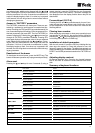
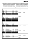
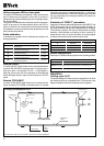
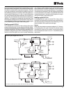
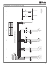
Operation
Cooling cycle YLCC
The heat exchanger for water acts as an evaporator unit, while
the finned coil acts as a condenser unit. The summer cycle
diagram indicates the circuit followed by the refrigerant.
Cooling cycle diagram for YLCC
The units are made up of two circuits, with common water connections.
CONDENSER
SCROLL
COMPRESSOR
EVAPORATOR
EXPANSION
VALVE
FILTER-DRYER
SIGHT
GLASS
CENTRIFUGAL
FAN