


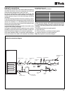

23
Hydraulic connections
The hydraulic connections of the water intake and outlet of
the chiller should be carried out respecting the intake and
outlet directions indicated at the front of the unit.
An iron (not galvanised) or copper tubing can be use, with
dimensions no lower than those indicated, and keeping in
mind the pressure drops of the indoor exchanger and of the
installation.
Pump dimensioning should be carried out considering a nomi-
nal flow that allows the ∆t of the project within the limits of the
unit: min. 3° C and max. 7° C. The head pressure of the pump
chosen must cover the pressure drops of the installation plus
the pressure drops of the chiller.
It is convenient that the tubing connection be carried out by
means of anti-vibratory couplings.
In all cases, a flow switch must be installed so as to avoid the
possibility of operation without water circulation, as well as a
water filter (both are obligatory for warrantee application).
In the water feedback tubing, an expansion vessel adequate
to the total volume of the water in the installation should also
be installed in the unit.
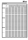
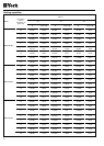
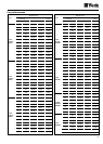
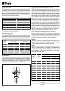
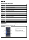
Chiller water volume is as follows:
During the winter season, with outdoor temperatures below
0° C, precautions should be taken to avoid the water from
freezing in the tubing networks and inside the inner chiller
exchanger.
The following solutions are usually applied:
a) Drain the circuit.
b) Fill the circuit with an antifreeze mixture (glycol).
c) Keep the circulator in constant operation.
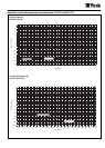
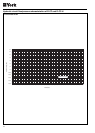
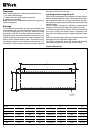
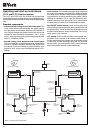
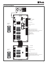
Note: See hydraulic connections diagram.
WATER GAUGE
BUFFER TANK
(IF NECESSARY)
ISOLATOR
VALVE
SAFETY
VALVE
PURGER
AUTOMATIC FILLING
ASSEMBLY
FLOW SWITCH
THERMOMETERWATER GAUGE
DRAIN
EXPANSION
VESSEL
FLEXIBLE GASKET
FILTER
CIRCULATING
PUMP
FLEXIBLE GASKET
YLCC
YLCC-H
Size Litres
42 25
62 28
82 38.2
102 38.2
122 78.5
152 73.5
Hydraulic connections diagram