


24
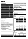
YLCC / YLCC-H Litres
42 200
62 260
82 260
102 600 S
122 600 S
152 600 P
l/h l/s m WG kPa
42 6 700 1.86 15 147
62 10 100 2.8 15 147
82 13 500 3.75 15 147
102 17 200 4.77 15 147
122 19 900 5.53 15 147
152 25 800 7.16 15 147
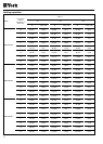
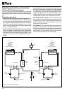
Approximate pump
flow ∆t 5°C
Minimum pressure supplied
by the pump
YLCC/
YLCC-H
unit
Hydro kits GH
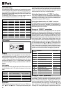
To avoid discomfort caused by a water temperature drop in
the defrost cycle, or tripping of the antifreeze thermostat in
small volume installations, it is necessary to use an accumu-
lator tank to increase the thermal inertia of the installation.
Water volumes of the GH kits and their compatibility with the
YLCC/YLCC-H units are as follows:
Nevertheless, in each case the minimum volume needed for
the installation should be checked.
Circulating pump
For satisfactory operation of the units, it is essential to select
an adequate pump to supply sufficient flow and pressure to
the hydraulic circuit. Use the following table for this purpose.
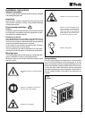
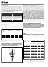
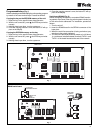
Flow switch
The hydraulic circuit to which the unit is connected is equipped
with a flow switch that avoids operation of the air conditioner
without sufficient water flow. The installation of this switch is
absolutely indispensable, as well as checking correct setting
and operation during installation commissioning.
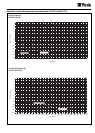
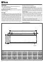
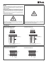
Application to YLCC/YLCC-H units
These flow switches can be used on water or glycol circulat-
ing tubing. They are designed for locking; that is to sea, pro-
tection against a lack of liquid circulation. The switch is to be
mounted on horizontal tubing, in a section having a straight
run of at least five times the tubing diameter on each side of
the flow switch. Do not install near valves, elbows or open-
ings. Installation should be such that terminals are accessi-
ble for easy connection. The switch is marked with the flow
direction. For 1" tubing, mount the switch on a standard 1" x
1" x 1" tee joint. Use a reducer tee on larger size tubing to
keep the flow switch set to same and achieve an adequate
length of the tab in the flow current. Example: use a 2" x 2" x
1" tee for 2" tubing. If a standard tee is used, install a buffer or
sleeve at the top of the opening. Adjust the tab length to the
tubing size. For 1", 2" or 3" tubing, us the tab segments sup-
plied. For example: for 2" tubing remove the 3" tab; for 1 ½”
tubing, cut the tab to the tubing size or use the 1" tab.
L/min. flow values needed for switch operation
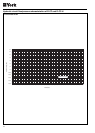
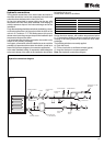
No part of the tab should touch the tubing or narrowing points
of same. Screw flow switch on in a position in which the plane
of the tab is in right angle to the flow. The arrow appearing on
the side of the box should point in the flow direction.
Setting
This switch is factory-set approximately at the minimum flow
value (see “Flow values table”). To achieve a higher flow value,
turn the adjusting screw on the scale clockwise.
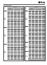
Flows
This table shows adjustable flows based on real test data,
using 1", 2" and 3" vanes for 1-6" tubing. The differential (dif-
ference between ON and OFF) depends upon flow condi-
tions. (Flows for “flow increase” that appear in parenthesis
are predetermined values.)
Note: Flow decrease: Flow at which the switch is activated when flow
decreases.
Flow increase: Flow at which the switch is activated when flow
increases.
1" 1 18 (21) 45 (50)
1 1/4" 1 43 (46) 100 (102)
1 1/2" 1 63 (68) 140 (145)
2" 1 105 (120) 250 (255)
2 1/2" 1 195 (200) 565 (570)
3" 1 360 (370) 850 (880)
2" 2 50 (50) 150 (155)
2 1/2" 2 105 (120) 355 (360)
3" 2 170 (180) 480 (490)
Vane
dia.
Adjustable flow (litres/minute)
Tubing
dia.
Min. Max.
Flow
increase
Flow
decrease
Flow
increase
Flow
decrease