


37
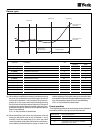
Heat exchange takes place between the liquid (water or water
and glycol) and the refrigerant in the coaxial heat exchanger.
The water is cooled and the evaporates refrigerant. Then the
Scroll type compressor compresses the refrigerant (gas) until
the condensing pressure is reached, which then goes on to
the air cooled condensing unit. In the air cooled condensing
unit, heat exchange takes place between the air and the re-
frigerant. The air is heated and removed from the chiller (heat
rejection). The refrigerant is condensed and subcooled. Then
the refrigerant (liquid) goes on to the expansion valve where it
is expanded down to the evaporating pressure, and then goes
on to evaporating unit to begin a new cooling cycle.
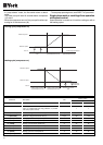
Cooling cycle YLCC-H
The 4-way valve is not activated. Heat exchange takes place
between the liquid (water or water and glycol) and the refriger-
ant in the coaxial heat exchanger. The water is cooled and the
refrigerant evaporates. Then the Scroll type compressor com-
presses the refrigerant (gas) until the condensing pressure is
reached, which then goes on to the air cooled condensing
unit. In the air cooled condensing unit, heat exchange takes
place between the air and the refrigerant. The air is heated
and removed from the chiller (heat rejection). The refrigerant
is condensed and subcooled. Then the refrigerant (liquid) goes
on to the expansion valve where it is expanded down to the
evaporating pressure is reached, and then goes on to evapo-
rating unit to begin a new cooling cycle.
Heating cycle YLCC-H
In heating mode this cycle is inverted. The 4-way valve is
activated. The condensing unit becomes the evaporating unit,
and the evaporating unit becomes the condensing unit. The
water is heated in the coaxial heat exchanger.
Defrost
When the probe detects a temperature below 0.5° C (factory-
set freezing point), this cycle is inverted. The defrost cycle is
activated for a maximum of 4 minutes. If, during this period of
time, the temperature rises to over +6° C, the defrost cycle is
deactivated.
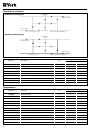
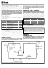
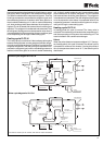
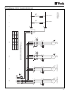
Summer cycle diagram for YLCC-H
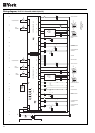
Winter cycle diagram for YLCC-H
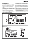
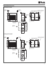
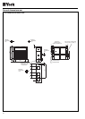
The units are made up of two circuits, with common water connections.
CONDENSER
4-WAY VALVE
COMPRESSOR
SUCTION
ACCUMULATOR
EVAPORATOR
REVERSIBLE
EXPANSION
VALVE
FILTER-DRYER
LIQUID
ACCUMULATOR
CENTRIFUGAL
FAN
SIGHT
GLASS
CONDENSER
4-WAY VALVE
COMPRESSOR
SUCTION
ACCUMULATOR
EVAPORATOR
REVERSIBLE
EXPANSION
VALVE
FILTER-DRYER
LIQUID
ACCUMULATOR
CENTRIFUGAL
FAN
SIGHT
GLASS