


12
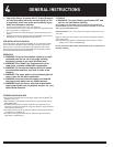
GAS INSTRUCTIONS
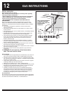
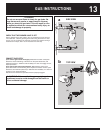
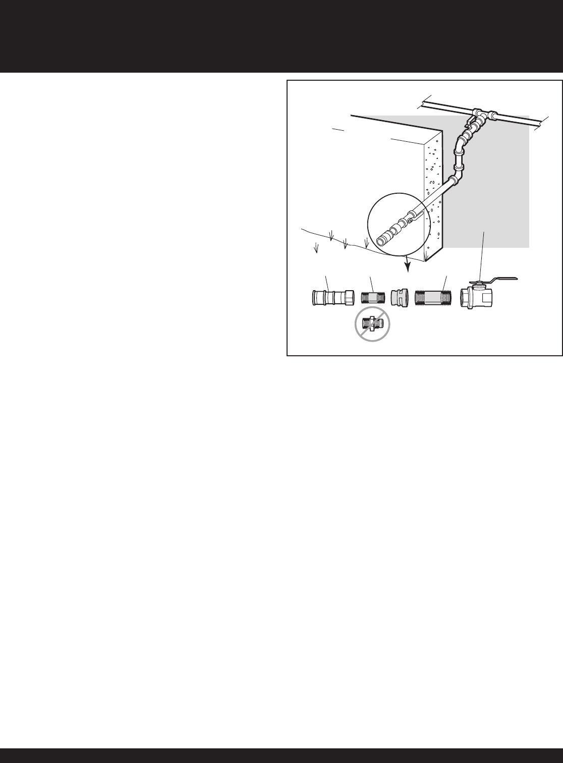
Gas supply
Shut off
Locking shut off
Inside wall
Outside wall
Quick
disconnect
3
/
8
" Pipe
nipple
1
/
2
" Pipe
nipple
Do Not Use
This is a typical installation
of a Weber
®
natural gas
fireplace. Local codes may
require different
installations.
INSTALL GAS SUPPLY
General Specifi cations for Piping
Note - Contact your local municipality for building codes regulating
outdoor gas fi replace installations.
• Refer to AS5601 gas installations for piping and hose requirements.
• Refer to AS5601/AG 601, local authority, gas, electric, and other
relevant statutory regulations for use and installation.
• WE RECOMMEND THAT THIS INSTALLATION BE DONE BY A
PROFESSIONAL.
Some of the following are general requirements taken from the latest
edition of the National Fuel Gas Code: ANSI Z 223.1/NFPA 54, or CAN/
CGA-B149.1, see Natural Gas and Propane Installation Code for complete
specifi cations.
• This fi replace is designed to operate at 4 inches of water column
pressure (.2526 psi).
• The maximum inlet gas pressure for this fi replace is 7 inches of water
column pressure.
• A manual shut-off valve must be installed outdoors, immediately ahead of
the quick disconnect.
• An additional manual shut-off valve indoors should be installed in the
branch fuel line in an accessible location near the supply line.
• The quick disconnect connects to a 3/8 inch NPT thread from the gas
source. The quick disconnect fi tting is a hand-operated device that
automatically shuts OFF the fl ow of gas from the source when the
fi replace is disconnected.
• The quick disconnect fi tting can be installed horizontally, or pointing
downward. Installing the fi tting with the open end pointing upward can
result in collecting water and debris.
• The dust covers (supplied plastic plugs) help keep the open ends of the
quick disconnect fi tting clean while disconnected.
• Pipe compound should be used which is resistant to the action of natural
gas when connections are made.
• The outdoor connector must be fi rmly attached to rigid, permanent
construction.
ƽ WARNING: Do not route the 10 foot hose under a
deck. The hose must be visible.
Gas Line Piping
• If the length of the line required does not exceed 50 feet, use a 5/8" O.D.
tube. One size larger should be used for lengths greater than 50 feet.
• Gas piping may be copper tubing, type K or L; polyethylene plastic tube,
with a minimum wall thickness of .062 inch; or standard weight (schedule
40) steel or wrought iron pipe.
• Copper tubing must be tin-lined if the gas contains more than 0.3 grams
of hydrogen sulfi de per 100 cubic feet of gas.
• Plastic tubing is suitable only for outdoor, underground use.
• Gas piping in contact with earth, or any other material which may corrode
the piping, must be protected against corrosion in an approved manner.
• Underground piping must have a minimum of 18" cover.
• Installation and repair should be done by a qualifi ed service person.
The fi replace should be inspected before use and at least annually by
a qualifi ed service person. More frequent cleaning may be required
as necessary. It is imperative that control compartment, burners and
circulating air passageways of the fi replace be kept clean.
Test Connections
All connections and joints must be thoroughly tested for leaks in accordance
with local codes and all listed procedures in the latest edition of the National
Fuel Gas Code: ANSI Z 223.1/NFPA 54, or CAN/CGA-B149.1.