


21
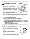
Step 31: Installing Wireless Keyless Entry (If Included)
Install all wall controls out of the reach of children and in a location where the
door can be seen before activating.
CAUTION: The keypad should be mounted a minimum of 5 feet from the floor to keep it out
of the reach of small children.
Locate a convenient place to mount the Wireless Keyless Entry. Choose a convenient location
that does not interfere with the normal opening and closing of the door. To keep keyless entry out
of the reach of children, measure and mark a spot at least five feet up from the floor. Use the drill-
ing template located on Page 32 to determine hole positions. Drill 5/64” pilot holes 3/4" deep at
each screw location.
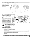
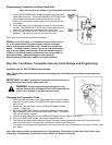
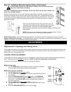
Snap open the Wireless Keyless Entry case with a coin. Se-
cure keyless entry base into wood wall framing using the two
screws provided. Snap the front case half with the base.
Remove paper backing from instruction label and apply to a clean surface
inside garage.
NOTE: Two screws are included for mounting to wood structures. Ensure
proper hardware is used for mounting to other materials.
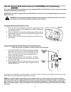
Battery Replacement: Under normal operating conditions, the batteries should be changed once every 12 months.
Dispose used batteries properly. To change batteries, snap open case with a coin and remove old batteries. Insert two
CR2032 or equivalent coin cell batteries and snap case together.
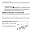
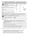
Adjustment # 1 Opening and Closing Force
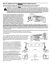
This garage door opener is built with a safety system that allows the door to reverse in the close direction and stop in the
open direction. This must be adjusted so your opener does not use excessive force in the down direction or react to the
weight of the door during upward travel.
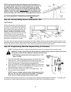
CLOSING FORCE ADJUSTMENT
To help determine that the closing door force is not excessive, grasp the door handle or bottom edge during downward
travel. The opener should REVERSE
to this force. NOTE: Do not stand under door during this test.
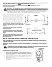
To adjust the closing force follow one of the two methods listed below.
Method A (manual)
1. Turn the FORCE ADJ. (see illustration) counter clockwise to decrease
force and repeat reversal test until door reacts properly.
Method B (computer assisted)
1. Operate the door to the fully open
position.
2. Turn the FORCE ADJ. (see illustration) counter clockwise to the minimal
force setting.
3. Press the PROGRAM SWITCH button two
times or the PROGRAM
button on the Wireless Wall Station (if included) until the LED turns on
solid (5 sec.). The STATUS LED and the overhead lamp will flash on
and off at a slow rate.
4. Operate the door to the fully closed
position.
5. Turn the FORCE ADJ. clockwise until the STATUS LED flickers or just
turns off.
6. Press the PROGRAM SWITCH once to confirm setting.
A
DJUSTMENTS