


18
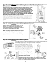
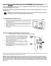
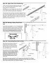
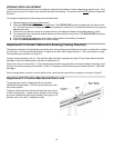
Step 24: Upper Door Arm Positioning
Trolley must be at the factory preset fully close posi-
tion. If not, activate opener to bring trolley to factory
preset close limit, (see illustration).
CAUTION: Door arm will swing down when tie wrap
is cut. Support upper arm
with your free hand, to
prevent door arm from swinging down unexpectedly.
The upper door arm is secured to the spacer bracket with one
tie wrap during shipping. Remove tie wrap attaching upper
door arm to the spacer bracket, this will allow door arm to
swing down. Slide the trolley until it snaps on the chain latch
assembly. Attach warning label and red pull knob to red
release cord connected to trolley.
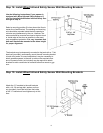
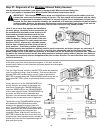
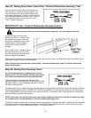
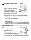
Step 25: Setting Trolley Close Posi-
tion
Verify trolley close position is 11” to 13” between trolley
clevis pin and the inside face of the door. If adjustment
of the trolley position is required, use the close travel
adjustment screw located on the bottom of the motor
head. A 1/4 turn equals approximately 1” of trolley travel;
turn clockwise to decrease distance (forward) and
counter-clockwise to increase distance (backward).
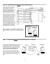
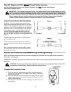
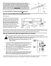
Step 26: Connecting Door Arm to Door
Align lower door arm hole in curved end
(single hole) with middle hole of door
bracket. Install 5/16” clevis pin through
lower door arm and door bracket, slide
5/16” flat washer over clevis pin and se-
cure with retaining ring.
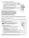
Align upper and lower door arm pieces to
nearest matching holes. Note: It may be
necessary to apply downward pressure
on the door or slightly raise the door
during this process. Secure upper and
lower door arms to each other using two
1/4-20x3/4” machine bolts and 1/4-20
nylock nuts.
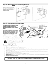
Note: Door arm angle must be 10° to 30° degrees (see illustration). If not, repeat
Step 25 and increase distance between trolley clevis pin and inside face of the door.
Note: Install machine bolts as far apart as possible.