


13
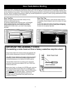
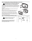
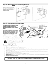
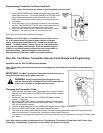
Step 18: Mount Wired Infrared Safety Sensors
Attach the sending and receiv-
ing units to the “U” brackets by
inserting their tabs into their
respective holes.
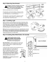
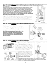
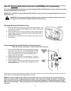
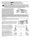
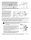
Step 19: Connecting Electrical Power
To reduce the risk of electrical shock,
connect the power cord only to a
properly grounded 3 prong, 120 volt
outlet.
Do not use an extension cord or change
the plug in any way. At this point, plug in
the opener to an electrical outlet. If the
plug does not fit into the outlet, or you
require permanent wiring, contact a
qualified electrician to install the proper
outlet. As soon as power is applied to
the unit, the light on the opener will blink
once to indicate a successful self-check of the controls.
Check your local electrical codes. If your
local code requires permanent wiring,
use the specifications called for and in-
structions illustrated.
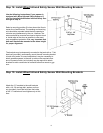
Permanent Wiring Procedure
1. Ensure line cord is disconnected from power source.
2. Cut line cord 1/2” – 1” from strain relief / bushing.
3. Use needle nose pliers to remove strain relief bushing from frame. Squeeze tabs in on underside of bushing and
work bushing out of hole.
4. Pull or strip off remaining section of outer insulation from three conductors of line cord. Pull the three wires into
the operator. Discard remaining line cord.
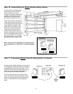
5. Strip 1/2" of insulation from the black, white, and green wires.
6. Using UL/CSA approved wire nuts for 14-18AWG wire, wire nut black-black, white-white, and green-green (earth)
wires securely.
7. Replace Power Head Unit cover.
DO NOT USE AN ELECTRICAL EXTENSION CORD OF ANY TYPE