


Please Do Not Return This Product To The Store. Contact your local Wayne-Dalton dealer. To find your local Wayne-Dalton dealer,
refer to your local yellow pages business listings or go to the Find a Dealer section online at www.wayne-dalton.com
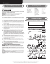
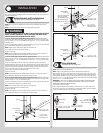
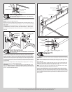
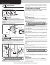
Top bracket slide
5/16”-18
Flange hex nut
Horizontal track
Roller
Top section
End Bearing Brackets
14
Tools: Step ladder, Power drill, Ratchet wrench, 7/16” Socket driver,
9/16” Socket, 9/16” Wrench
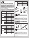
IMPORTANT: RIGHT AND LEFT HAND IS ALWAYS DETERMINED FROM INSIDE THE BUILDING
LOOKING OUT.
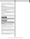
NOTE: End brackets are right and left hand.
Attach the left hand end bearing bracket through either the end bearing bracket’s upper or
IMPORTANT: THE END BEARING BRACKET’S LOWER SLOTS ARE USED ON DOORS WITH
12” RADIUS TRACK; THE UPPER SLOTS ARE USED ON DOORS WITH 15” RADIUS TRACK.
other side.
(2) 3/8”-16
Hex nuts
(2) 3/8”-16 x 3/4”
Truss head bolts
Left end bracket
Upper slot
Lower slots
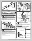
Horizontal angle
(3) 5/16” x 1-5/8”
Lag screws
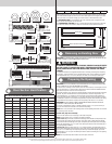
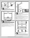
Center Bearing Bracket
15
Tools: Step ladder, Power drill, 7/16” Socket driver, 1/4” Torx bit, Level,
Tape measure, Pencil
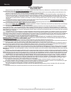
Locate the center of the door. Mark a vertical pencil line on the mounting surface above
the door, at the center. Measure from the center of the bearing, in one of the end bearing
brackets, downwards, to the top the door. Using that measurement, measure that distance
upwards from the top of the door to the mounting surface, and mark a horizontal pencil line
which intersects the vertical pencil line. Align the edge of the center bearing bracket with
the vertical pencil line and the center of the bearing in the center bearing bracket with the
horizontal pencil line; this is to ensure the torsion tube is level between the center and end
bearing brackets.
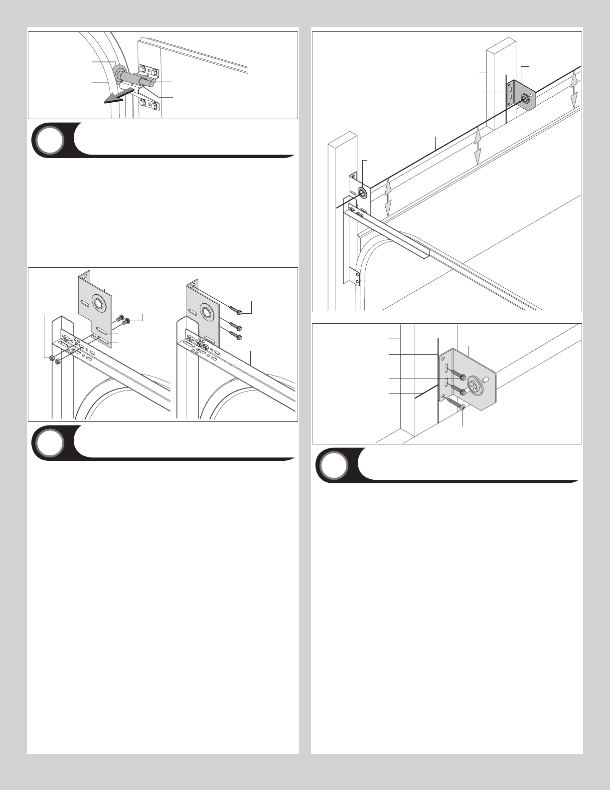
screws and (1) 5/16” x 2” tamper-resistant lag screw.
IMPORTANT:
5/16” X 2” TAMPER-RESISTANT LAG SCREW IF MOUNTING SURFACE IS MOUNTED OVER
MASONRY. TAMPER-RESISTANT LAG SCREW MUST BE ATTACHED THROUGH THE BOTTOM
HOLE OF THE CENTER BEARING BRACKET.
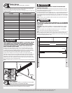
Center bearing
bracket
Vertical line
Mounting surface
Equal distance (top of door section to horizontal line)
Horizontal line
Center of end
bearing bracket
Center bearing
bracket
(1) 5/16” X 2” or (1) 5/16” x 1-5/8”
Tamper-resistant lag screw
(2) 5/16” x 1-5/8”
Lag screws
Vertical line
Mounting surface
Horizontal line
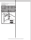
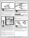
Spring Assembly
16
Tools: Step Ladder
IMPORTANT: RIGHT AND LEFT HAND IS ALWAYS DETERMINED FROM INSIDE THE BUILDING
LOOKING OUT.
NOTE: Identify the springs provided as either right hand wound (red winding cone), which
goes on the LEFT HAND SIDE or left hand wound (black winding cone), which goes on the
RIGHT HAND SIDE.
Facing the inside of the door, lay the torsion tube on the floor. Lay the spring with the black
winding cone and the black cable drum at the right end of the tube. Lay the spring with the
red winding cone and the red cable drum at the left end of the tube.
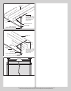
NOTE: The set screws used on all torsion winding cones and cable drums are now colored
red. DO NOT identify right and left hand by the set screw color.
Slide the center bearing bracket onto the torsion tube followed by the springs and cable
drums. The center bearing bracket, springs, and cable drums must be positioned as shown.
With assistance, pick up the torsion assembly and slide one end of the torsion tube through
one end bearing bracket and the other end of the torsion tube through the other end bearing
bracket. Position the torsion tube so that equal amounts of the tube extend from each end
bearing bracket.
9