


Please Do Not Return This Product To The Store. Contact your local Wayne-Dalton dealer. To find your local Wayne-Dalton dealer,
refer to your local yellow pages business listings or go to the Find a Dealer section online at www.wayne-dalton.com
for other side.
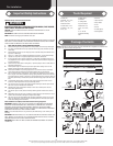
Top section
(4) 1/4”-20 x 5/8”
Self drilling screws
Top bracket assembly
3”
Roller
End cap
Top Section
10
Tools: Hammer, Step ladder, Tape measure
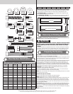
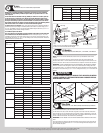
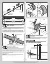
Place the top section in the opening. Temporarily secure the top section by driving a nail in
the header near the center of the door and bending it over the top section. Now, flip up the
hinge leaves, hold tight against section, and fasten center hinges first and end hinges last
(refer to step, Stacking Sections). Vertical track alignment is critical. Position vertical track
assembly’s flag angle between 1-11/16” (43 mm) to 1-3/4” (44 mm) from the edge of the
door; tighten the bottom lag screw. Flag angles must be parallel to the door sections. Repeat
for other side.
IMPORTANT: THE DIMENSION BETWEEN THE FLAG ANGLES MUST BE DOOR WIDTH PLUS
Complete the vertical track installation by tightening the other lag screws. Push the vertical
track against the rollers so that the rollers are touching the deepest part of the curved side of
the track as shown; tighten all the track bolts and nuts. Repeat for other side.
Top section
Top
section
Nail
Door width
+ 3-3/8” to 3-1/2”
1-11/16”
to 1-3/4”
Flag
angle
Flag angle
Vertical track
against rollers
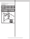
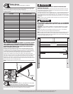
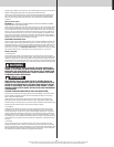
Operator Bracket
11
Tools: Power drill, 7/16” Socket driver, Tape measure
NOTE: If you did not receive an operator bracket, skip this step.
IMPORTANT: WHEN CONNECTING A TROLLEY TYPE GARAGE DOOR OPENER TO THIS DOOR,
A WAYNE-DALTON OPERATOR/ TROLLEY BRACKET MUST BE SECURELY ATTACHED TO
THE TOP SECTION OF THE DOOR IF ONE HAS BEEN PROVIDED, ALONG WITH ANY U-BARS
PROVIDED WITH THE DOOR (IF A WAYNE-DALTON OPERATOR/ TROLLEY BRACKET WAS NOT
PROVIDED WITH YOUR DOOR, THAN USE THE ONE PROVIDED BY YOUR OPERATOR MANU-
FACTURER). THE INSTALLATION OF THE OPERATOR MUST BE ACCORDING TO MANUFAC-
TURER’S INSTRUCTIONS AND FORCE SETTINGS MUST BE ADJUSTED PROPERLY.
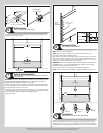
Uninstall the centermost hinge connecting the top section to the one below by removing the
bolts and flange nuts.
Slide the top of the upper half of the operator bracket under the u-bar, removing the u-bar’s
screws if necessary, and attach to the top section (through u-bar if necessary) using (3) 1/4”-
NOTE: If your door lacks a U-bar on the top section, ignore the previous paragraph.
Position the bottom half of the operator bracket so that its hinge is located at the section joint
between the top section and the one below. The bottom two holes should be on the section
below the top section and the two holes above should be on the top section. Attach using (4)
NOTE: When attaching operator bracket to top section with u-bar, apply additional pressure
to thread into the u-bar.
(4) 1/4”- 20 x 5/8”
Self-drilling screws
(3) 1/4”- 20 x 7/8”
Self-drilling screws
(4) 5/16”- 18 x 3/4”
Bolts and nuts
Upper half
U-bar
Lower half
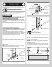
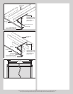
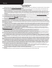
Attaching Hor Tracks to Vertical Tracks
12
Tools: Ratchet wrench, 7/16” Socket, 9/16” Socket, 9/16” Wrench,
level, Step ladder
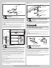
To install horizontal track, place the curved end over the top roller of the top section. Align the
bottom of the horizontal track with the top of the vertical track. Tighten the horizontal track to
the flag angle with (2) 1/4”-20 x 9/16” track bolts and (2) 1/4”-20 flange hex nuts.
WARNING WARNING
DO NOT RAISE DOOR UNTIL HORIZONTAL TRACKS ARE SECURED AT REAR,
AS OUTLINED IN STEP, REAR SUPPORT, OR DOOR COULD FALL FROM OVER-
HEAD POSITION CAUSING SEVERE OR FATAL INJURY.
Level the horizontal track assembly and bolt the horizontal angle to the first encountered slot
other side.
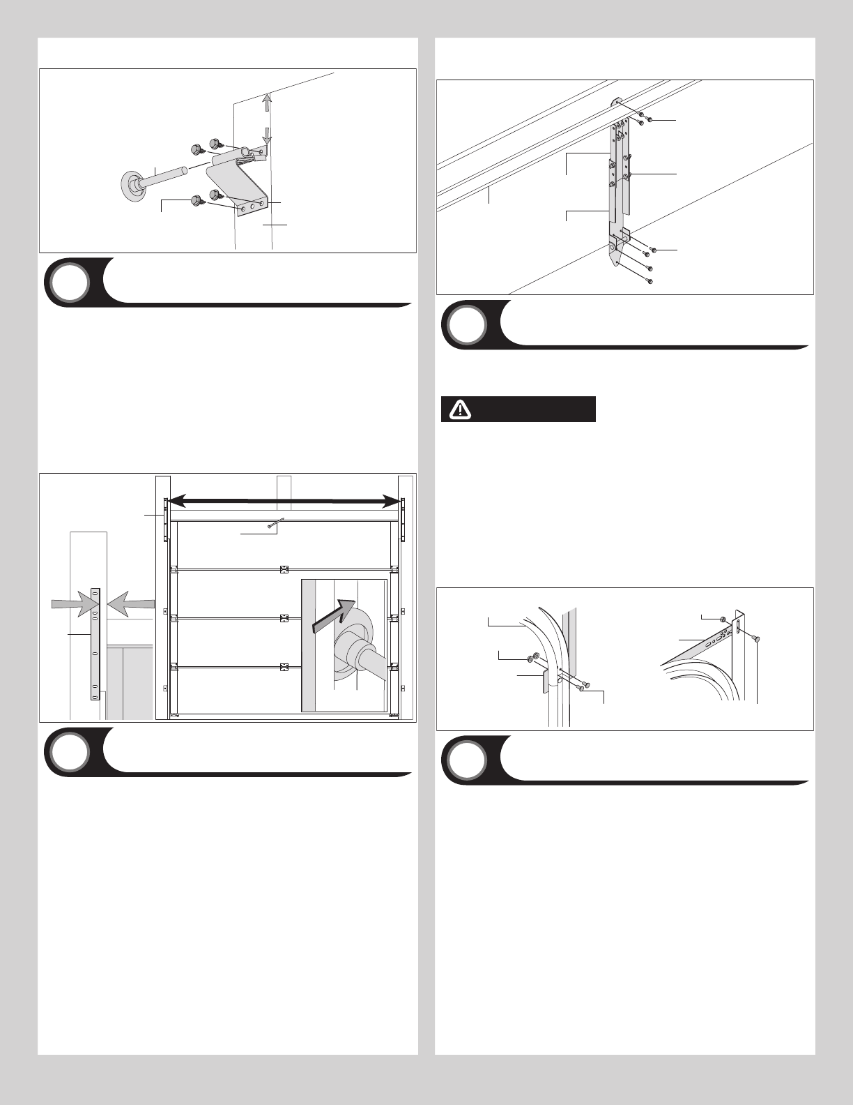
Remove the nail that was temporarily holding the top section in place, installed in step, Top
Section.
IMPORTANT: FAILURE TO REMOVE NAIL BEFORE ATTEMPTING TO RAISE DOOR COULD
CAUSE PERMANENT DAMAGE TO TOP SECTION.
NOTE: If an idrive
®
opener will be installed, position horizontal tracks slightly above level.
Flag angle
1/4”-20 x 9/16”
Track bolts
1/4”-20
Flange hex nuts
Horizontal
track
3/8”-16
Hex nut
Horizontal
angle
3/8”-16 x 3/4”
Truss head bolt
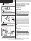
Adjusting Top Brackets
13
Tools: 7/16” Wrench, Step ladder
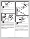
With horizontal tracks installed, you can now adjust the top brackets. Vertically align the top
section of the door with the lower sections. Once aligned, position the top bracket slide out
to secure the top bracket slide to the top bracket base.
Secure the slide further with (1) 1/4”-20 x 9/16” track bolt and (1) 1/4”-20 flange hex nut
through any of the holes in the top bracket slide.
If your windload option code is 0124, secure all of the door’s rollers with 7/16” push nuts by
placing a push nut onto the end of each roller and sliding it toward the end hinge or bracket.
Leave at least 1/4” of space between push nut and end hinge or bracket.
8