


Please Do Not Return This Product To The Store. Contact your local Wayne-Dalton dealer. To find your local Wayne-Dalton dealer,
refer to your local yellow pages business listings or go to the Find a Dealer section online at www.wayne-dalton.com
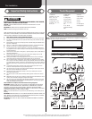
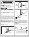
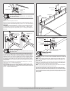
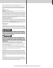
U-bars
3
Tools: Power drill, 7/16” Socket driver, Tape measure
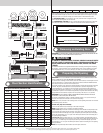
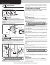
NOTE: Refer to strutting schedules to determine placement of u-bars. Strutting
schedules are separated by windload option codes; X’s represent where a u-bar
will be placed.
U-bars will either be attached at the top, middle, or bottom of a section; if placed
across the top of a section the u-bar will be placed just below the hinge leaf at
the top of the section (except for u-bar placement on top section, which is simply
the top of the section); if placed across the bottom of a section, the u-bar will be
placed high enough on the section to ensure the hinge leafs of an adjoining section
will have clearance once sections are stacked and fastened together.
To attach a U-bar to a section: Place U-bar against section (refer to strutting schedule to
determine placement) and align it horizontally with section. Attach to section using (2) 1/4”-
For windload option code 0124:
The u-bar that is to be attached across the bottom of the bottom section will need
to be installed across the bottom brackets.
self drilling screws from each bottom bracket. Place u-bar across section and attach to bot-
additional fasteners as stated above.
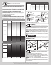
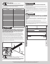
Door
Section Quantity
Section Placement (top, middle, or bottom of section)
Top Middle Bottom
3 Bottom X X
Lock X X
Top X X
4 Bottom X X
Lock X X
Intermediate X X
Top X X
5 Bottom X X
Lock X X
Intermediate X X
Intermediate II X X
Top X X
6 Bottom X X
Lock X X
Intermediate X X
Intermediate II X X
Intermediate III X X
Top X X
Door
Section Quantity
Section Placement (top, middle, or bottom of section)
Top Middle Bottom
3 Bottom X
Lock X
Top
4 Bottom X
Lock X
Intermediate
Top X
5 Bottom X
Lock X
Intermediate
Intermediate II X
Top X
6 Bottom X
Lock X
Intermediate
Intermediate II X
Intermediate III X
Top X
(2) 1/4”-20 x 5/8”
Self drilling screws
End hinge
Intermediate
hinge
Fasten u-bars at all end hinge and intermediate hinge
locations, as well as locations between hinges.
U-bar
U-bar
(2) 1/4”-20 x 5/8”
Self drilling screws
(2) 1/4”-14 x 5/8” Self
drilling screws between
hinge locations
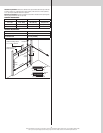
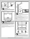
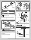
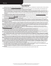
Lift Handles
4
Tools: Tape Measure, Power Drill, 9/32”, 1/2” Drill Bit, 7/16” Wrench
NOTE: Refer to door section identification, located in the pre-installation section of this
manual.
Locate the vertical center of the lock (second) section of the door and position the lift
handle’s bottom hole 4” from the bottom of the lock section along the vertical center on the
outside of the door. Use the holes in the lift handle as a template to mark the hole locations.
IMPORTANT: THE LIFT HANDLE AND THE STEP PLATE NEED TO BE VERTICALLY ALIGNED.
Drill 9/32” diameter holes through the section at each marked location. Enlarge the holes
from outside the door to 1/2” diameter through the section. Assemble the outside and inside
lift handles to the section using (2) 1/4” x 2-1/2” carriage bolts and (2) 1/4”-20 hex nuts and
spacers.
WARNING WARNING
TO AVOID POSSIBLE INJURY, LIFT HANDLES THAT ARE INSTALLED WITHIN
4 INCHES (102MM) OF A SECTION INTERFACE SHALL PROMOTE VERTICAL
ORIENTATION OF THE HAND.
(2) Spacers
1/2” Diameter holes
(2) 1/4” x 2-1/2” Carriage bolts
Lift handle
Lock section
outside
Lock section
inside
4”
Lift handle
(2) 1/4”-20 hex nuts
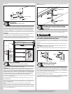
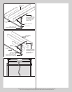
Step Plate
5
Tools: Power drill, 7/16” Drill bit, Phillips screwdriver, Tape measure
On the bottom door section, locate the vertical center of the door.
On the inside of the door, center the inside step plate’s second top most hole and bottom
bottom of the door to the top of the step plate. Drill 7/16” diameter holes through the entire
section at these hole locations. Be careful to keep drill straight.
IMPORTANT: -
TION.
Insert the outside step plate into the holes through the front of the door, and mount the two
into the outside step plate.
6