


Please Do Not Return This Product To The Store. Contact your local Wayne-Dalton dealer. To find your local Wayne-Dalton dealer,
refer to your local yellow pages business listings or go to the Find a Dealer section online at www.wayne-dalton.com
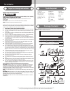
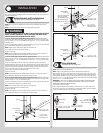
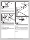
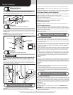
Outside step plate
Bottom section outside
Holes enlarged
to 7/16” diameter
Inside step plate
Bottom section inside
Pre-punched
holes
(2) #8 x 1-1/2” screws
8” Max.
mounting
height
Bottom Section
6
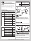
Tools: Level, Wooden shims (if necessary)
Center the bottom section in the door opening. Level the section using wooden shims (if
necessary) under the bottom section.
Weather seal
Level
Bottom section
Wooden shims
(If necessary)
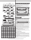
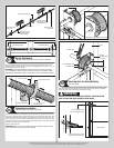
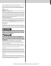
Vertical Track Assemblies
7
Tools: Power Drill, 3/16” Drill bit, 7/16” Socket driver, Tape measure,
Level, Step ladder
IMPORTANT: THE TOPS OF THE VERTICAL TRACKS MUST BE LEVEL FROM SIDE TO SIDE.
IF THE BOTTOM SECTION WAS SHIMMED TO LEVEL IT, THE VERTICAL TRACK ON THE
SHIMMED SIDE MUST BE RAISED THE HEIGHT OF THE SHIM.
Position the left hand vertical track assembly over the rollers of the bottom section. Make
sure the counterbalance cable is located between the rollers and the door jamb. Drill 3/16”
pilot holes into the door jamb for the lag screws.
-
tom section and vertical track. Now, tighten all remaining lag screws.
Repeat for other side.
Vertical
track
assembly
5/16” x 1-5/8”
Lag screws
3/8” to 5/8”
Spacing
Bottom section
Vertical track
Bottom
section
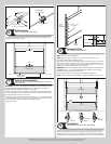
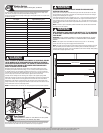
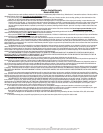
Stacking Sections
8
Tools: Power drill,7/16” Socket driver
NOTE: Refer to door section identification.
NOTE: Make sure hinges are flipped down, when stacking another section on top.
Place rollers into end hinges of remaining sections.
With assistance, lift second section and guide rollers into the vertical tracks. Lower section
until it is seated against bottom section. Flip hinges up. Fasten intermediate hinge(s) first
drilling screws. Repeat for other sections, except top section.
IMPORTANT: PUSH & HOLD THE HINGE LEAFS SECURELY AGAINST THE SECTIONS WHILE
BETWEEN THE HINGE LEAFS AND THE SECTIONS.
Ensure all jamb brackets are secured tightly to the vertical tracks and jambs.
NOTE: Install lock at this time (sold separately). See optional installation step, Side Lock.
Lock section
Vertical
tracks
Intermediate
hinge(s)
Left
end hinge
Right
end hinge
1/4”-14 x 7/8” Self drilling screw locations
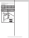
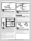
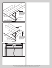
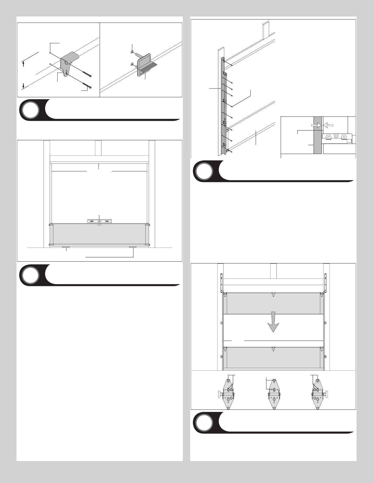
Top Brackets
9
Tools: Power drill, 7/16” Socket driver, Tape measure
Align the top bracket assembly 3” down from the top section and even with the edge of the
section, the slotted half of the bracket base should be facing upwards. Fasten to section
and adjusted later, in step, Adjusting Top Brackets. Insert roller into top bracket slide. Repeat
7