


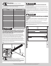

INSTALLATION
Before installing your door, be certain that you have read and followed all of the instruc-
tions covered in the pre-installation section of this manual. Failure to do so may result in an
improperly installed door.
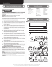
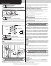
Bottom Brackets and Counterbalance
1
Tools: Power drill, 7/16” Socket driver, 1/4” Torx bit
NOTE: Refer to door section identification, located in the pre-installation section of this
manual.
NOTE: Cable drums and bottom brackets are marked right and left hand.
WARNING WARNING
FAILURE TO ENSURE TIGHT FIT OF CABLE LOOP OVER MILFORD PIN COULD
RESULT IN CABLE COMING OFF THE PIN, ALLOWING THE DOOR TO FALL,
POSSIBLY RESULTING IN SEVERE OR FATAL INJURY.
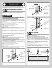
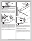
For doors with bottom brackets shown in top illustration: Attach left hand bottom
bracket to the left corner of the bottom section, making sure it is seated to the edges of the
self drilling screw.
Uncoil the counterbalance cables from the drums, making sure you place the left hand cable
loop on the left hand milford pin of the bottom bracket.
NOTE: Check to ensure cable loop fits tightly over the milford pin.
Insert a roller into spacer and the bottom bracket.
Repeat for other side.
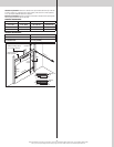
NOTE: Verify astragal (bottom seal) is aligned with door section. If there is more than 1/2”
excess astragal on either side, trim astragal even with door section.
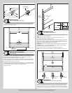
For doors with bottom brackets shown in middle illustration: Attach left hand bottom
bracket to the left corner of the bottom section, making sure it is seated to the edges of the
self drilling screw.
Uncoil the counterbalance cables from the drums, placing the left hand cable loop into
position between the two holes on the side of the left hand bottom bracket. Slide a clevis pin
through the innermost hole, cable loop, and outermost hole, of the bottom bracket. Slide a
washer onto the clevis pin and secure in place by inserting a cotter pin into the hole of the
clevis pin. Bend the ends of the cotter pin outwards to secure it in place.
Insert a roller into spacer and the bottom bracket.
Repeat for other side.
NOTE: Verify astragal (bottom seal) is aligned with door section. If there is more than 1/2”
excess astragal on either side, trim astragal even with door section.
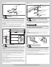
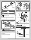
For doors with bottom brackets shown in bottom illustration: Attach left hand bottom
bracket to the left corner of the bottom section, making sure it is seated to the edges of the
Uncoil the counterbalance cables from the drums, making sure you place the left hand cable
loop on the left hand milford pin of the bottom bracket.
NOTE: Check to ensure cable loop fits tightly over the milford pin.
Insert a roller into spacer and the bottom bracket.
Repeat for other side.
NOTE: Verify astragal (bottom seal) is aligned with door section. If there is more than 1/2”
excess astragal on either side, trim astragal even with door section.
Counterbalance
cable loop
(2) 1/4”-14 x 7/8”
Self drilling screws
Bottom section
1/4”-14 x 5/8”
Tamper resistant
self drilling screw
Roller
Milford pin
Bottom
bracket
End cap
Spacer
Bottom section
(4) 1/4”-14 x 7/8”
Self drilling screws
1/4”-14 x 5/8”
Tamper resistant
self drilling screw
Counterbalance
cable loop
Cotter pin (attached into
place from opposite
side of bottom bracket)
Clevis pin (inserted through
cotter pin and bent into place)
Washer
Roller
Bottom
bracket
End cap
Spacer
Counterbalance
cable loop
(5) 1/4”-14 x 7/8”
Self drilling screws
Bottom section
Roller
Milford pin
Bottom
bracket
End cap
Spacer
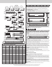
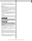
Hinge Attachment
2
Tools: Power drill,7/16” Socket driver
NOTE: Refer to door section identification.
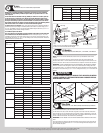
NOTE: Hinges can be identified by the number stamped onto their lower leaf.
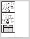
Align the lower leafs of the #1 end hinges over the holes at the top of the end caps of the
bottom section, and align the lower leafs of the #1 intermediate hinges with the dimples at
the intermediate locations at the top of the section. Attach lower leafs of end hinges to sec-
IMPORTANT: PUSH & HOLD THE HINGE LEAF SECURELY AGAINST THE SECTION WHILE
BETWEEN THE HINGE LEAF AND THE SECTION.
Place a roller into each end hinge.
Repeat hinge attachment for all remaining sections except the top section, using #2 end
hinges for the lock section, #3 end hinges for the intermediate section, and #4 end hinges
for the intermediate II section, if such a section was provided.
#1Intermediate
hinge(s)
#1 End hinge
Roller
Lower leaf
#2 End hinge
(roller inserted into tube
furthest from section)
(3) 1/4”-14 x 7/8” Self
drilling screw locations
(2) 1/4”-14 x 7/8” Self
drilling screw locations
Please Do Not Return This Product To The Store. Contact your local Wayne-Dalton dealer. To find your local Wayne-Dalton dealer,
refer to your local yellow pages business listings or go to the Find a Dealer section online at www.wayne-dalton.com
5