


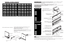
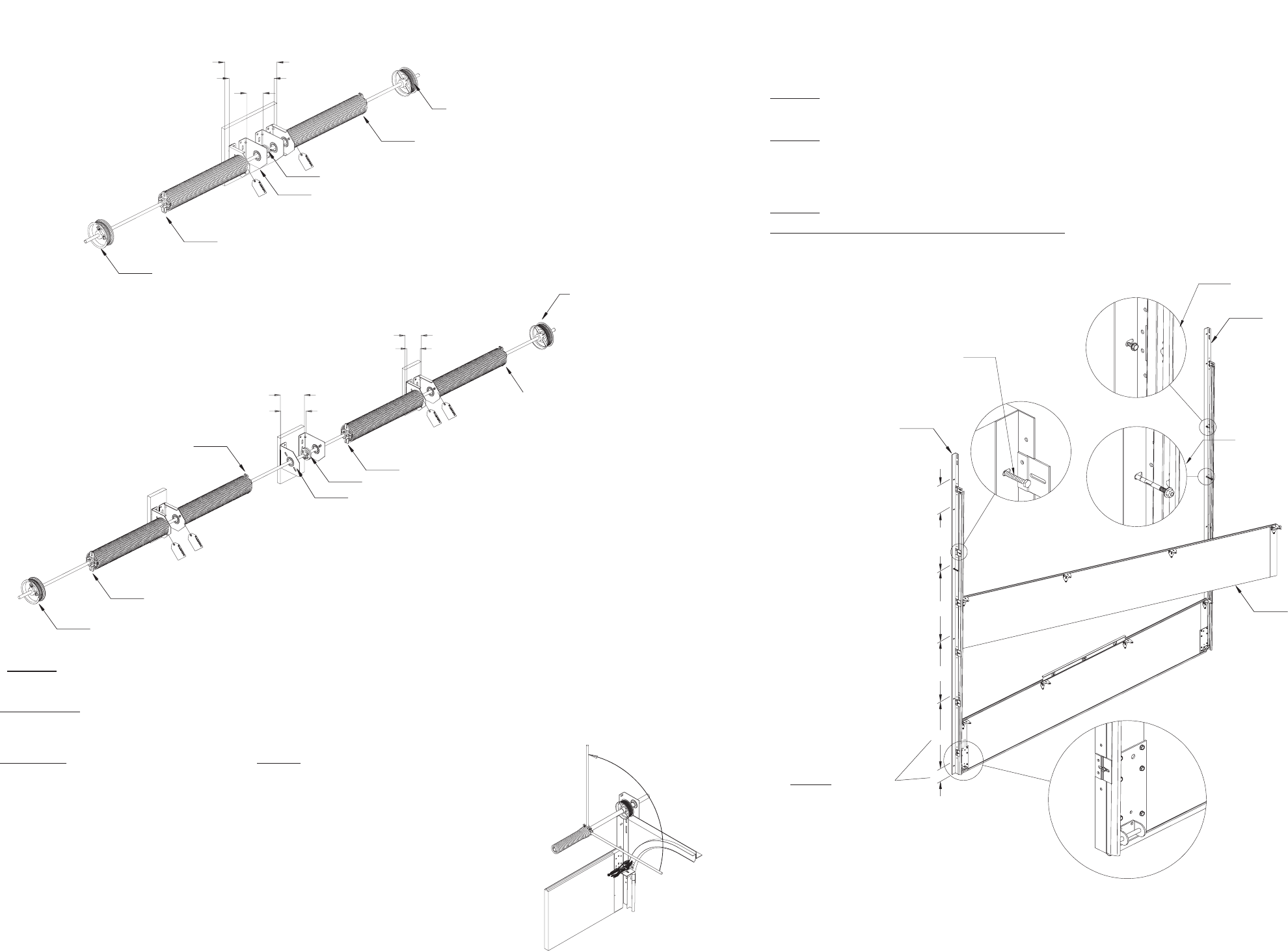
5/16 X 1 Self drilling & tapping screw
for use on steel jambs.
3/8 X 3 Sleeve anchor for use on
pre-cast concrete.
( Drill a 3/8 x 3-1/2 deep hole)
5/16 X 1 5/8 Lag
screw for use on
wood jambs.
Angle out (wood
jambs)
Reverse angle
(steel or precast/block)
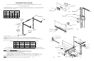
13
30or
18
24
24
24
10
NOTE: Typical
fastener spacing.
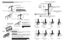
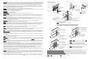
Install hardware onto left side of
section, install roller into vertical
track, rotate the section into
position and stack, align sections
and secure right hand hardware.
Fig. L
PG. 7
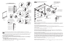
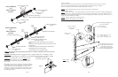
Wind springs toward ceiling.
(Standard lift applications)
PG. 10
Fig. M
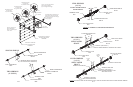
RIGHT HAND DRUM
BLACK
EXTRA SUPPORT BRACKET USED WITH SPLIT SHAFT
COUPLING (SEE NOTE * )
LEFT HAND DRUM
RED
WINDING CONE
RED
WINDING CONE
BLACK
TWO SPRINGS
(6)
SPLIT SOLID
SHAFT
13
20
24 MINIMUM SPRING PAD
WIDTH
FOUR SPRINGS
(6)
SPLIT SOLID
SHAFT
EXTRA SUPPORT BRACKET USED
WITH SPLIT SHAFT
COUPLING (SEE NOTE * )
8 MIN.
SPRING
PA D
7
12 MIN.
PA D
WIDTH
13
WINDING CONE RED
WINDING CONE BLACK
RIGHT HAND DRUM
BLACK
WINDING CONE BLACK
WINDING CONE RED
LEFT HAND DRUM
RED
spacing is achieved.
Doors over 11 ft. high and over 14ft. wide must have (1) intermediate drop hanger as shown in Fig. S on Page 13.
Doors between 16 and 18 high must have (2) intermediate drop hangers as shown in Fig. S on Page 13.
Doors over 18 high must have intermediate drop hangers placed on 6 centers.
STEP 13: Release the locking pliers from vertical track and check the doors counterbalance.
Adjust springs if necessary.
STPE 14: Vertical tracks can now receive final adjustments. Open and close the door a few times, checking and adjusting side
clearance (if necessary). Tighten jamb fasteners (lags, teks, or anchors) to permanently secure verticals. Adjust door in or out
from jamb by loosening the track to obtain proper seal. Permanently tighten all track bolts. Adjust top bracket roller carrier so
that the top section is sealed against header.
STEP 15: Lubricate springs, rollers, and bearing with oil.
DO NOT GREASE THE INSIDE OF THE TRACKS.
WARNING: Apply locking pliers to the tracks ABOVE the third
roller, or lock door if applicable, before winding the spring(s) to
prevent door from rising unexpectedly, possibly resulting in severe
injury or death.
Wind spring 1/4 turn at a time to the number of complete revolutions
recommended on the spring tag. Wind up as shown Fig. M. When the
proper number of turns is reached, tighten the set screws on the
winding cone. Release the vice grips from the spring shaft(s). Adjust
the coupler on split solid shafts until drums are in time (check door
level) and tighten coupler.
WARNING: Winding bars must fit snuggly into holes in spring winding cones. Attempting to wind
springs with loosely fitting rods, screwdrivers or other improper tools can result in sever injury or death.
*
NOTE: COUPLING USED ON SOLID SHAFT ONLY. TIGHTEN CONNECTING BOLTS AFTER
WINDING SPRING.
RED WINDING CONES ALWAYS POINT TO THE LEFT
SIDE
BLACK (OR PLAIN) WINDING CONES ALWAYS POINT THE
RIGHT SIDE,
STANDING INSIDE OF THE BUILDING, LOOKING OUT.
RED DRUMS GO ON THE LEFT SIDE
BLACK DRUMS GO ON THE RIGHT SIDE