


PG. 5
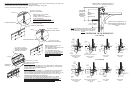
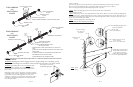
STEP 4. MODEL 5150 & 5200 U-bars & struts to be secured to the section using (2) 1/4 - 20 x 7/8 TEK screws at each end.
Additional 1/4 - 20 x 7/8 TEK screws will need to be used at each hinge location.
U-bars and struts are to be mounted at the top of section under hinges and across top brackets, as seen in Fig. K. Refer to
STRUTTING SCHEDULE for strut placement.
NOTE: Strut clips used at top bracket. If strutting is required for a raised panel, glazed section, place
U-bar over hinge leaf and attach with 1/4 self-drilling/tapping screws and strut clips.
STEP 4. MODEL 5155 & 5255 U-bars are to be secured to the sections using 1/4 - 20 x 7/8 TEK screws and strut clips. Mount
U-bars at top of section, across hinge leafs and top brackets.
Fig. K
(Top (2) Section Shown)
Top bracket installation illustration.
Secure each bracket using (4) 1/4
- 20 x 7/8
self-drilling/tapping screws and (2)strut clips.
Doors over 142 wide require double top
brackets.
Place (2) 1/4 - 20 x 7/8
self-drilling/tapping screws
at each hinge location.
3 U-Bar
Fasten using (2) 1/4 - 20 x 7/8
self-drilling/tapping screws at each
hinge location.
Fasten using (4) 1/4-20 x 7/8
self-drilling/tapping screws.
Attach Girt at end of section
using (4) 1/4-20 x 7/8
self-drilling/tapping screws.
6 Girt
Door Widths Strutting
8’ 0" - 10’ 2" None
10’ 3" - 14’ 2" (1) 2" U-Bar
(1) 3" U-Bar
Every Other Section
(1) 3" U-Bar (20 Ga.)
Every S ection
(1) 3" U-Bar (16 Ga.)
Every Section Plus 1
(1) 6" Girt
Every Other Section
Door Widths Strutting
8’ 0" - 10’ 2" None
10’ 3" - 12’ 2" (1) 2" U-Bar
(1) 3" U-Bar
Every Section Plus 1
(1) 3" U-Bar (20 Ga.)
Every S ection
(1) 3" U-Bar (16 Ga.)
Every Section Plus 1
(1) 6" Girt
Every Other Section
5150 & 5155 Strutting Schedule
Standard Section Reinforcement
Non-Brown Doors
20’ 3" - 26’ 2"
18’ 3" - 20’ 2"
16’ 3" - 18’ 2"
14’ 3" - 16’ 2"
20’ 3" - 26’ 2"
Brown Doors
12’ 3" - 16’ 2"
16’ 3" - 18’ 2"
18’ 3" - 20’ 2"
Door Widths Strutting
8’ 0" - 12’ 2" None
12’ 3" - 14’ 2" (1) 2" U-Bar
(1) 2" U-Bar
Every Other Section
(1) 3" U-Bar
Every Section Plus 1
(1) 3" U-Bar (20 Ga.)
Every Section Plus 1
(1) 6" Girt
Every Other Section
Door Widths Strutting
8’ 0" - 10’ 2" None
10’ 3" - 12’ 2" (1) 2" U-Bar
(1) 2" U-Bar
Every Other Section Plus 1
(1) 3" U-Bar
Every Other Section Plus 1
(1) 3" U-Bar (20 Ga.)
Every Section Plus 1
(1) 6" Girt
Every Other Section
5200 & 5255 Strutting Schedule
Standard Section Reinforcement
Non-Brown Doors
14’ 3" - 16’ 2"
16’ 3" - 18’ 2"
18’ 3" - 20’ 2"
20’ 3" - 26’ 2"
16’ 3" - 18’ 2"
18’ 3" - 20’ 2"
20’ 3" - 26’ 2"
Brown Doors
12’ 3" - 16’ 2"
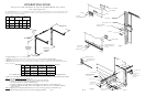
STEP 5. Center and level (or support to a known grade level) the bottom section in the opening, as seen in Fig. K. Temporarily
attach the vertical tracks to the jambs. Allow 1/2 clearance between the section and the track as illustrated in the sideroom
illustrations (page 3).
It is important that the top of each track is at the same level. (shim if necessary)
Products being installed to precast or block must use a 3/8 x 3 long sleeve anchor to attach the verticals to the building. Use the
slots in the wall angle as a drill template, drill a 3/8 hole (3-1/2 deep) and secure to anchor.
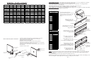
SPRING TURN CHART
DOOR HEIGHT 400-8 400-12 5250-18 800-32
6’6" 7 1/2 7 1/2
7’0" 7 7/8 7 7/8
7’6" 8 1/2 8 1/2
8’0" 8 7/8 8 7/8 6 3/4
8’6" 9 1/4 7 1/8
9’0" 9 1/2 7 3/8
9’6" 10 1/8 7 3/4
10’0" 10 1/2 8 1/8 5 3/8
10’6" 11 8 3/8 5 5/8
11’0" 11 1/2 8 7/8 5 7/8
11’6" 12 9 1/8 6
12’0" 12 1/2 9 1/2 6 1/4
12’6" 9 7/8 6 1/2
13’0" 10 1/4 6 3/4
DOOR HEIGHT 400-8 400-12 5250-18 800-32
13’6" 10 1/2 7
14’0" 10 7/8 7 3/8
14’6" 11 1/4 7 1/2
15’0" 11 1/2 7 5/8
15’6" 11 7/8 8
16’0" 12 1/4 8 1/8
16’6" 12 1/2 8 1/4
17’0" 12 7/8 8 5/8
17’6" 13 1/4 8 7/8
18’0" 13 1/2 9
18’6" 9 1/4
19’0" 9 1/2
19’6" 9 3/4
20’0" 9 7/8
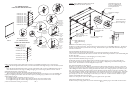
Broken Cable Safety
Device (SES)
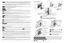
Broken Cable Safety Device Installation
5/8 X 20 self-drilling
TEK screw (8)
Cable Arm
Cable Arm
PG. 12
Fig. R
1-1/2 X #10 Counter
Sunk Bolt (3)
Exhaust Port
Gasket
Fig. X
Gasket
#10 Hex Nuts (3)
(1) Attach the broken cable safety device, with cable attached, to the section
using (8) 1/4-20 X 5/8 self-drilling TEK screws (as seen in Fig. R.).
(2) Place the bottom section in the opening.
(3) Install the verticals over the rollers.
(4) Follow the rest of the door installation per the instruction manual.
(5) After the door installation is complete, rotate the cam arm up, and connect the
cable arm to the cam arm with the clevis and cotter pins.
(6) Operate the door to verify that there is clearance between the track and section
for the cable arm.
(7) Adjust the track as needed.
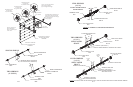
6 Girt
Fasten using (2) 1/4-20 x 7/8
self-drilling/tapping screws and
(1) L Bracket at each hinge location.
Install L Bracket over lower hinge leaf.
(1) 1/4-20 x 7/8
self-drilling/
tapping screws
.
Strut clips are
required, on
raised panel,
glazed sections
(Top Section Shown)
Fasten using (2) 1/4 - 20 x 7/8
self-drilling/tapping screws at each
hinge location.
Fasten using (5) 1/4 - 20 x 7/8
self-drilling/tapping screws and
(1) L Bracket at each hinge location.
5150/5200
Girt Attachment
5155/5255
Girt Attachment
Outside Trim Ring
#10 X 1-1/2 BOLT
W/LOCK NUT
Cam Arm
Cam Arm