


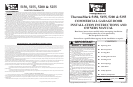
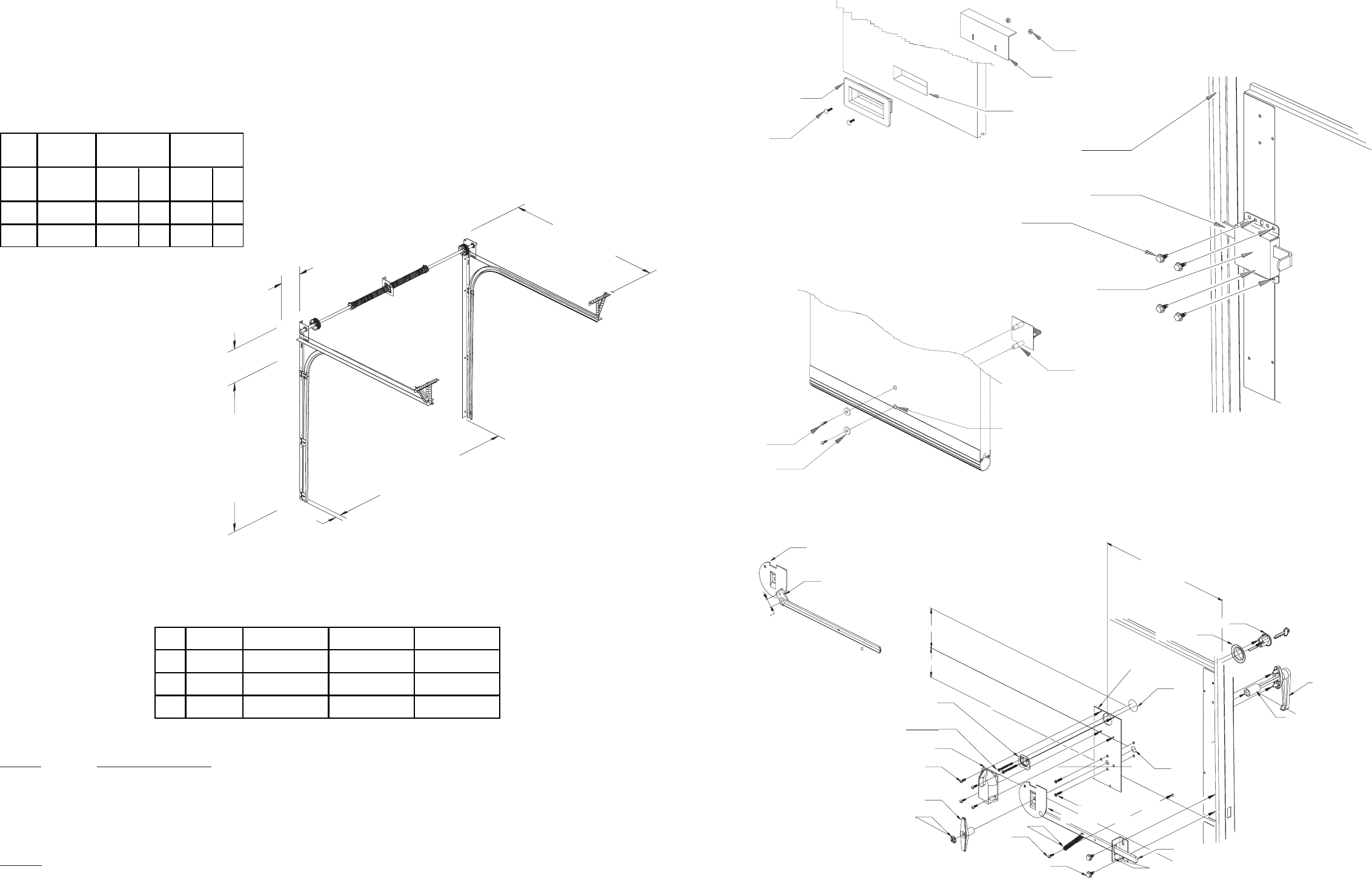
HEADROOM
A
B
SIDE ROOM
DAYLIGHT
OPENING
HEIGHT
BACKROOM
DAYLIGHT
OPENING
WIDTH
SIDE ROOM
OPERATING ZONE
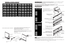
You Can Save Time And Effort If You First Establish All The Facts About
The Operating Zone
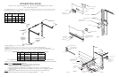
HEADROOM CHART For Standard Lift Track (Minimum Distance Required)
Dim. Y INDICATES THE DISTANCE FROM THE HEADER TO THE CENTER LINE OF TORSION SHAFT.
NOTE: 2 1/2 OF ADDITIONAL HEADROOM IS REQUIRED FOR SINGLE TROLLEY OPERATOR INSTALLATIONS.
TRACK DEPTH
SIZE INTO
ROOM
STEEL
and WOOD SOLID TUBE
MASONRY
DOOR HEIGHT
PLUS 18"
DOOR HEIGHT
PLUS 24"
DIM. B
SIDEROOM
TORSION SHAFT
5"
3" 10" 5"
2-1/2" 3-1/2" 10"
3"
DIM. A
SIDEROOM
TRACK
2"
5"
3" TRACK 2" TRACK 2" TRACK
15" RADIUS 15" RADIUS 12" RADIUS
400-8 HEADROOM 15 1/2" 15" 12"
400-12 DIM Y 13" 12 1/2" 9 1/2"
HEADROOM 17 1/2" 17" 14"
DIM Y 14 1/2" 14" 11"
HEADROOM 21" 20 1/2" NA
DIM Y 16 1/2" 16" NA
DRUMS DIMS
5250-18
800-32
PG. 2
1. Daylight Opening; Exact size of finished opening
2. Sideroom; required distance from the door opening to a wall or any obstruction. Refer To Sideroom Chart
3. Headroom; required distance from top of door opening to the ceiling or underside of joists. Refer To Headroom Chart
4. Backroom; required distance from door opening header to the furthest back point to which the door track or operator unit, and their
brackets, will extend.
The Operating Zone is the area surrounding the door opening, extending upward and backward as far as the door will travel. We call it
the Operating Zone because it is the area that the door will have to operate within and the dimensions are critical and must be known in
advance of a door and operator installation.
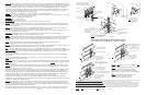
STEP 1. Verify The OPERATING ZONE Dimensions
A - Exact size of finished daylight opening. Do you have the correct door size?
B - Sideroom requirements for track and spring shaft. (Refer to sideroom chart)
C - Headroom requirements. (Refer to headroom chart)
D - Backroom (depth into room) Manual lift = Door height plus 18 Operators = Door height plus 48
E - Jambs must be plumb and solidly attached to the building. Floor must be level or exact gradeline established
before you start.
STEP 2. Shipping tags show important information, door size, track size and type, spring size and hardware type.
Verify that all material is present and correct before attempting installation.
PG. 15
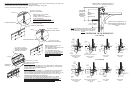
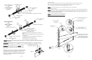
Vertical Track
5/8 X 20 self-drilling
TEK screws (4)
Align with slot in track
Outside Step Plate
3/16 holes drilled 1-3/16
and 3-3/8 from bottom
of section.
#8 Self-Tapping
Screw (2)
#8 Washer (2)
Rim Cylinder Plate
(2) 1-7/8 X #12 pan head
screws (broken to length
1-7/8 or 1-1/4
Inside T Handle
5/8 X 20 self-drilling
TEK screw (2)
Lock Plate
spring
Night Latch
Lock Bar
Cupped Lock Disk
Tinnerman Nut
(see note)
7/8
1-1/4
(2) #10 Pan head screws
(4) 3/4 X #8 screws
1/2 X #12
screw
Lock Plate
Trim Ring
12-1/2
Rim Cylinder
Lock Disk for 3 track
1/8 X 1-1/8 X 1-1/8
Steel welded to lock
plate
7/8 Extension
Side Lock
PG. 15
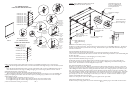
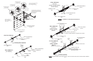
Fig. U
Fig. T
Fig. W
1/4 X 5/8
carriage bolt (2)
Step Dish
Cut Out
1/4-20 Nut (2)
Inside Step Plate
4-1/4
4
Outside Handle
1-5/16 PVC Spacer
5150 & 5155
1-11/16 PVC Spacer
5200 & 5255