


PG. 6
STEP 10: Position shaft(s) with spring system components to proper elevation, level and secure each end bracket to the horizontal
reinforcing angle using (2) 3/8 x 3/4 truss bolts and nuts. Anchor the wall mounting flange of the end bracket to the jamb
using (2) 5/16 x 1-5/8 lags (wood), (2) 5/16 x 1 self-drilling and tapping screws (steel), or (2) 3/8 x 3 sleeve anchors
(precast).
NOTE: Spring pads must be securely anchored before proceeding. The pads must by flush with the jambs.
Attach the spring support brackets to the pad(s) using the following fasteners:
Pre-Cast: Secure each spring support bracket using (2) 1/2 x 3 sleeve anchors. This installation will require the 1/2 anchors to
be secured to the building, then securing the brackets to the anchors as detailed in Fig. N Page 11.
Steel: Secure each spring support bracket using (3) 5/16 x 1 self-drilling and tapping screws as detailed in Fig. N Page 11.
Block Construction: Attach perforated angle 18 long to support bracket(s) using (2) 3/8 x 1-1/4 bolts and nuts. Chamfer angle
to clear top section high arc. Secure support brackets and perforated angle to block using (4) 3/8 x 2-1/2 sleeve anchors as
detailed in Fig. N Page 11.
Secure the stationary cone(s) (dead end) to the spring support bracket(s) using 3/8 bolts and nuts. Keep spring warning tags
clearly visible.
NOTE: The coupler support brackets only require (2) fasteners. The spring support brackets require (2) fasteners in the lower
slot and hole, then (1) fastener in the top slot.
WARNING: Failure to use proper number of fasteners can result in sudden spring tension release, causing severe injury or death.
NOTE: Each 3-3/4, 6 and Duplex spring is secured to a separate center support bracket. DO NOT attach two springs of this size
to one support bracket.
STEP 11: Feed the cable attached to the left hand bottom bracket up the vertical track, behind the roller shafts and secure to the
left hand drum. Push the drum up against the end bearing bracket and secure to the shaft by tightening the set screws (solid
shafts use 1/4 key(s) and set screws to secure drums).
Rotate drum and shaft until cable is taut, then apply vice grips to shaft, with end resting against header. This will hold cable taut
and on drum. There must be at least 1/2 wrap of cable on the drum. If not, contact Wayne-Dalton for proper length cables.
Attach other cable to right hand drum. Push drum against end bearing bracket and rotate drum until cable is taut. Secure drum
to shaft by tightening the set screws. Cable tension must be equal on both drums on single shaft applications. On split shaft
applications, apply vice grips to both shafts and secure bolts in coupling after springs are fully wound.
If top section is not installed, do so now, before winding springs. Make sure hardware is securely attached to all sections.
Carefully following spring winding instructions detailed in Fig. M on Page 10, wind spring(s), using the appropriate 1/2, 5/8 or
3/4 diameter winding rods of sufficient length.
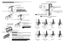
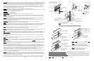
STEP 6. Secure the end hinges, (one side only) center hinges, and strutting ( if applicable) as previously illustrated. Locate the
Lock Section (usually the second section) and insert a roller into the end hinge. Stack this section into the opening by hooking the
roller in the vertical track and lowering it onto the bottom section. Insert a roller into the appropriate end hinge and insert roller
into vertical track on the opposite end. Secure end hinge to the section using the self-drilling and tapping screws. Align the
section edges, flip up the upper hinge leafs and secure to the lock section using the self-drilling and tapping screws. Continue to
hardware and stack the remaining sections in the proper sequence. Attach the top brackets to the upper corners, of the top
section, using self drilling and tapping screws as shown in Fig. J.
NOTE : Top section maybe installed now or may wait until the last step (installer preference)
STEP 7. Adjust the vertical track from 1/2 spacing at the bottom section to 3/4 at the top section. Refer to page 3. Permanently
secure each vertical to the jambs using the following fasteners:
Steel Jambs: 5/16 x 1 self drilling and tapping screw.
Wood Jambs: 5/16 x 1-5/8 lag screw.
Precast or Block: 3/8 x 3 sleeve anchor.
The left hand vertical track assembly indicates the standard fastener spacing (Fig. K page 7).
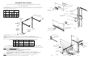
STEP 8: Use chain or cable to temporarily suspend the rear of the horizontal tracks. Secure the horizontal reinforcing angle to
the wall angle using (1) 3/8 x 3/4 truss bolt and nut, then secure the horizontal track to the splice plate or flagangle using (2)
track bolts and hex flange nuts.
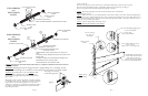
STEP 9: Torsion spring assemblies can be of several configurations depending on door size and weight. Left or right hand
spring(s) must be identified by the color of the winding cone. (Refer to Fig. L and pages 8-10)
Assemble torsion spring system components to applicable configuration shown on pages 8-10. Ensure that spring warning tags
are securely wired to all stationary spring cones.
WARNING: Install support brackets to solid structural members only. Do not install over dry wall or paneling.
NOTE: Use a chalk line or line level to ensure all support brackets are in line.
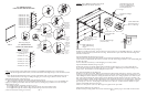
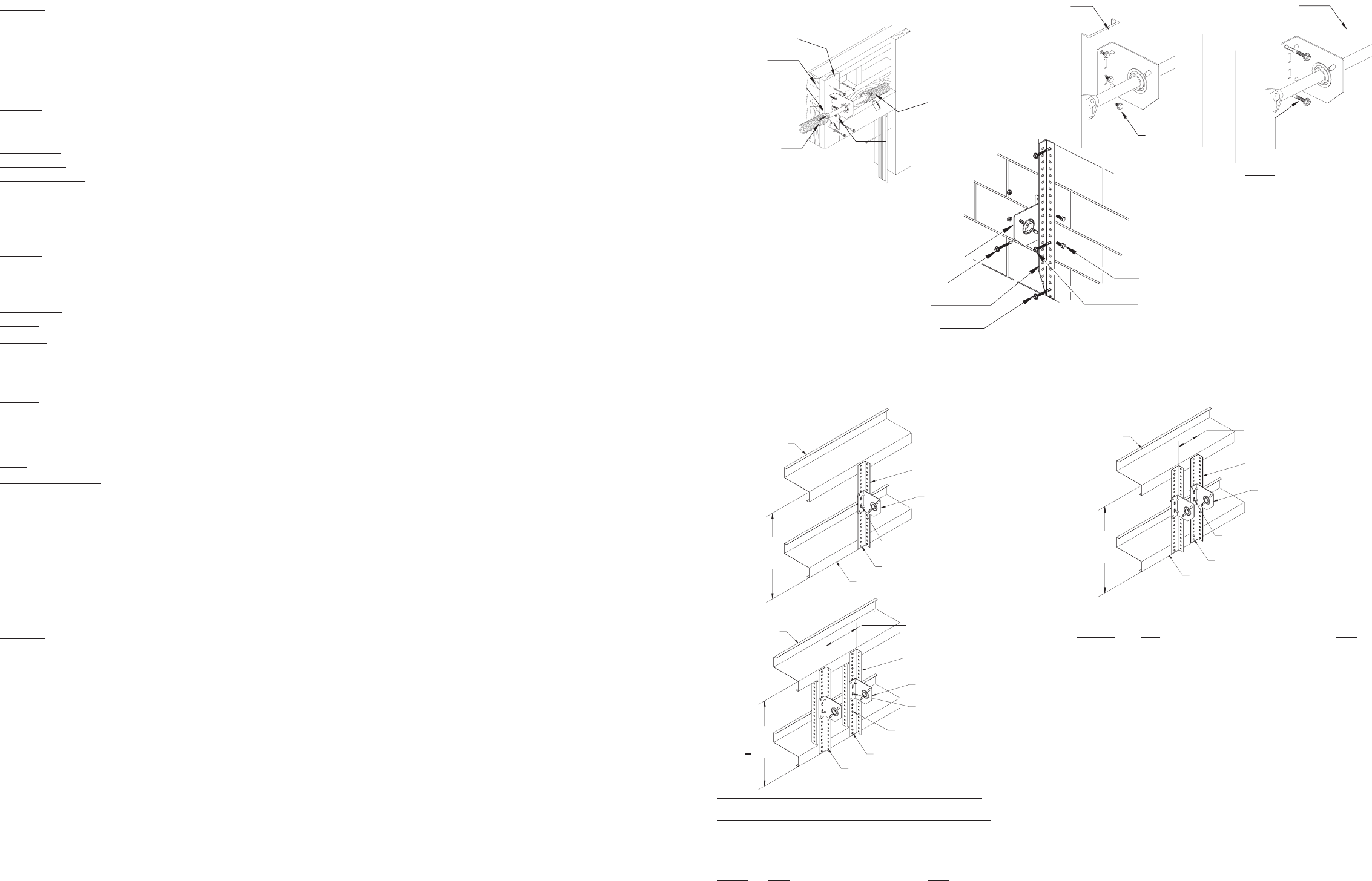
Fig. N
(2) 3/8 x 1 or
1-1/2 Bolts
(2) 3/8 Nuts
and Washers
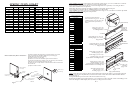
Spring mounting pad. 2 X 6 White
Pine or denser. Secured with min.
(4) 5/16 x 4 lag bolts into header.
Perimeter seal
Header
Top plate
1/2 x 3 Sleeve anchor
NOTE: Must secure sleeve
anchors to building first ,
then attach brackets to
anchors.
Pre-Cast
Bearing Bracket
Perforated Angle
(Trimmed to clear door high-arc)
Sleeve Anchor (4)
NOTE: All anchors must be positioned a
minimum of 1 from block edge.
3/8 X 1-1/4 Hex Head
Bolt and Nut (2)
Sleeve anchor positioned in
bottom slot of bearing bracket
Second anchor from bottom
must be below bearing
bracket
5/16 x 1 Self-drilling and
tapping screw
Steel
PG. 11
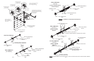
Alternate Steel Spring Pad Applications
Contact Manufacturer For Applications Not Covered Below
(2) 3/8 x 1-1/4 Bolts To
Secure Bracket To Angle
Heavy Perforated Angle
(1-5/8 x 2-3/8 x 11 GA.)
Center Spring Bracket
(2) 3/8 x 1-1/4 Bolts & Nuts
Top & Bottom
Girt
Girt
Space Center Brackets 12 - 14
Apart On Applications Requiring
Couplers
Bolt Z Shaped Assembly Using (4)
3/8 x 1-1/4 Bolts And Nuts
Y
(
< 7 ft.)
(2) 3/8 x 1-1/4 Bolts To
Secure Bracket To Angle
Heavy Perforated Angle
(1-5/8 x 2-3/8 x 11 GA.)
Center Spring Bracket
Girt
(2) 3/8 x 1-1/4 Bolts & Nuts
Top & Bottom
Girt
Y
(
< 7 ft.)
(2) 3/8 x 1-1/4 Bolts To
Secure Bracket To Angle
Heavy Perforated Angle
(1-5/8 x 2-3/8 x 11 GA.)
Center Spring Bracket
(2) 3/8 x 1-1/4 Bolts & Nuts
Top & Bottom
Girt
Girt
Space Center Brackets 12 - 14
Apart On Applications Requiring
Couplers
Y
(
< 7 ft.)
5/16 x 1-5/8
Lag Screws
Fig. AA
Fig. BB
Fig. CC
Maximum Door Size 9 x 9 (Maximum Door Weight 210 lb.) Fig AA: Cut perforated angle (1-5/8 x 2-3/8 x 11 GA.) to Dim Y. Thru-bolt top and bottom of angle to
each girt using (4) 3/8 x 1-1/4 bolts and nuts. Thru-bolt center bracket to perforated angle using (2) 3/8 x 1-1/4 bolts and nuts (See Fig. N-2).
Maximum Door Size 14 x 12 (Maximum Door Weight 400 lb.) Fig BB: Cut (2) perforated angle (1-5/8 x 2-3/8 x 11 GA.) to Dim Y. Thru-bolt top and bottom of
each angle to each girt using (4) 3/8 x 1-1/4 bolts and nuts. Thru-bolt each center bracket to perforated angle using (2) 3/8 x 1-1/4 bolts and nuts (See Fig. N-3).
Maximum Door Size 14-2 x 12-1 (Maximum Door Weight 800 lb.) Fig CC: Cut (2) pieces of perforated angle (1-5/8 x 2-3/8 x 11 GA.) to Dim Y and (2) more
pieces at Dim Y minus 3. Bolt the angles together into a Z shape using (4) 3/8 x 1-1/4 bolts and nuts. Thru-bolt top and bottom of each Z shaped angle to
each girt using (4) 3/8 x 1-1/4 bolts and nuts. Thru-bolt each center bracket to perforated angle assembly using (2) 3/8 x 1-1/4 bolts and nuts (See Fig. N-4).
NOTE: Do NOT Bolt (2) 3-3/4 Torsion Springs To ONE Center Bracket
NOTE: Do Not Bolt (2) 3-3/4 Torsion Springs to One
Center Bracket
NOTE: These Spring Mounting Techniques Are Not
Supported For 800-32, 6375-164, 1100-18, 1350-28,
& 800-120 Drums. These Instructions Are Also Not
Applicable For 5750-120 Drums With 72 Or More High-
Lift
NOTE: Maximum Spacing For Dimension Y is
84 in. (7 ft.) These Instructions Are Not
Applicable For A Span Greater Than 84 in.
STEP 12: After spring(s) are wound, cautiously remove locking pliers from vertical tracks, while pushing downward on door to
prevent it from raising unexpectedly, in case spring(s) were over wound. Carefully and slowly raise door, until one and a half
sections are in the horizontal tracks. Lock door in this position using locking pliers attached to vertical tracks above bottom roller
on one side and below bottom roller on other side of door.
Space the horizontal tracks 3/4 from section edge and level. Using 1-5/8 x 23/8 x 12 Ga. angle, fabricate back hangers and
attach them to building as shown in Fig. S on Page 13 using 3/8 bolts and nuts. Laterally brace all drop angles once proper