


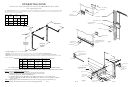
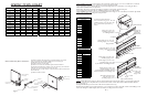
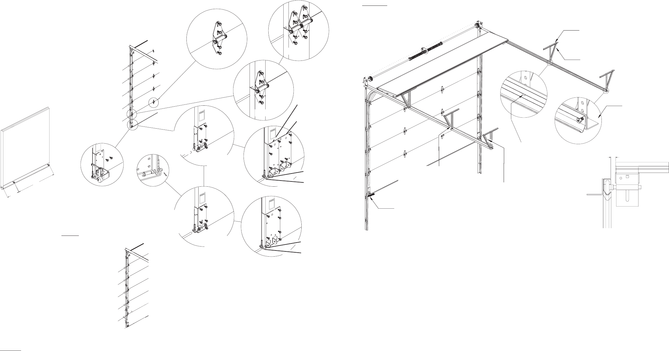
Intermediate hangers for all
doors over 11 high and over
14 wide. Positioned half way
between jamb and rear
hanger.
Lateral brace all hanger
angles.
Use a 3/8 X 3/4
truss bolt for roller
clearence.
3/8 dia. Bolt should
protrude into track to
serve as a roller stop.
Apply locking pliers to
secure while attaching
hangers.
Use 12 ga. minimum angle
(1-5/8 X 2-3/8)
3/4
Doors 16 to 18 use 2 inter-
mediate hangers.
Over 18 use hangers at 6
max. centers
NOTE: Use a chalk line or line level to ensure
all bearing brackets are in line. (± 1/8)
PG. 13
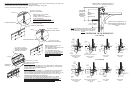
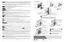
1/4 GRADUATION
8 SECTIONS HIGH OR LESS
FIG.A
5 to 8
18 o.c.
NOTE: For doors over 8
sections high and using
3 in. track, start with
(2) # 3 hinges, (2) #4 hinges,
(2) # 5 hinges, etc...
#3 HINGE (3in. Track)
#3 HINGE (3in. Track)
#4 HINGE (3in. Track)
#4 HINGE (3in. Track)
#5 HINGE (3in. Track)
1/8 GRADUATION
OVER 8 SECTIONS HIGH
Refer to Fig R Page 12.
#5 HINGE (2in. Track)
#7 HINGE (3in. Track)
#4 HINGE (2in. Track)
#6 HINGE (3in. Track)
#3 HINGE (2in. Track)
#5 HINGE (3in. Track)
#2 HINGE (2in. Track)
#4 HINGE (3in. Track)
#1 HINGE (2in. Track)
#3 HINGE (3in. Track)
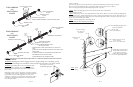
FIG.B
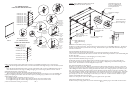
FIG. G
FIG.C
Secure Bracket
using (5) screws.
(No Spacer)
FIG.D
FIG.E
Secure Bracket
using (5) screws.
FIG. F
FIG.H
Single Wide 2
& 3 secure
using 5 screws
Double Wide 2
& 3 secure
using 10 screws
2 use 3/16
spacer
3 use 3/16
spacer
5200 & 5255
Single Wide
2 & 3
secure using
5 screws
2 use 3/16
spacer
3 use 1/2
spacer
5150 & 5155
Single Wide
2 secure
using 5 screws
Single Wide
2 secure
using 5 screws
STEP 3. Locate the bottom section, attach bottom seal using 1/4 self drilling and tapping screws as shown in Fig. A .
Locate the left and right hand bottom brackets, secure the counterbalance cable using clevis pin, washer and cotter key shown
in Fig. C
Locate the left and right hand bottom brackets, secure the counterbalance cable over the large milford pin shown in Fig. D
Secure bottom bracket to section using 1/4 drilling and tapping screws shown in Fig. E (for doors over 182 wide use
doublewide bottom brackets as shown in Fig. H)
(For doors using Broken Cable Safety Device Refer to Fig. B and page 12 Fig. R.)
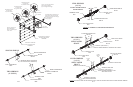
Align the appropriate end hinge to the pre-punched holes in the endstile and secure using (2) 1/4 x 5/8 self drilling and
tapping screws per hinge leaf. Products 142 wide and less require (1) end hinge (Fig. G) and doors over 142 wide require
double end hinges. (Fig. F)
The end hinge sequence is dependent on track size (2 or 3).
2 track applications begin with a number 1 hinge attached to the top corners of the bottom section.
3 track applications begin with a number 3 hinge attached to the top corners of the bottom section.
( Refer to the illustrations matching your track size)
Inside Side Lock Installation (See Fig. T Page 15)
Install lock on second section of door. Secure the lock to the section with (4) 5/8 x 20 self-drilling TEK screws. The side lock
should be spaced approximately 1/8 from the section edge. Ensure that lock is square with section and lock bolt aligns with
lock hole in vertical track.
Step Plate Installation 5150/5155 (See Fig. U Page 15)
At the desired location (typically below the lock) make two measurements from bottom of section and mark at
1-3/16 and 3-3/8. Drill 3/16 hole thru section at each mark. From the outside enlarge both holes to 7/16 without drilling thru
the inner skin of door.
Secure to 5150/5155 section with (2) 1 x #8 self-tapping screws and (2) washers..
Step Plate Installation 5200/5255 (See Fig. V Page 15)
Install outside step in pre-cut opening and bolt together with inside step plate using (2) 1/4 x 1 carriage bolts and nuts.
If your door does not have the pre-cut opening you can cut a 7-5/8 wide by 3 high opening 3 from the bottom edge of the
bottom section. This will need to be in vertical alignment with your lock.
Short Lock Bar Installation (See Fig. W Page 15)
Install lock on second section of door. Make two measurements from the bottom rib and mark at 4 and 8-1/4. These marks
must be 12-1/2 from section edge. Drill 1/4 hole thru section at each mark. From the outside enlarge the bottom hole to 7/8
without drilling thru the inner skin of door. Enlarge this hole in inner skin to 7/16. Enlarge top hole to 1-1/4 all the way thru
door section. Align inside lock plate with two holes in section and drill (2) 3/8 holes thru door section above and below 7/16
hole, using lock plate as template. Install outside handle to section with (2) #10 pan head screws and proper spacer. From inside
secure the rim cylinder to the section with (2) #12 pan head screws, broken to correct length. Secure the night latch to the lock
plate with (4) 3/4 x #8 screws. Attach spring to section with (1) 1/2 x #12 screw. Secure the inside T handle over square
shank of outside handle with push nut. (See note)
NOTE: Use a short piece of 7/16 to 1/2 ID steel pipe to tap push nut onto square shank.
Exhaust Port Installation (See Fig. X Page 12)
Install the exhaust port using (3) #10 x 1-1/2 counter sunk bolts and nuts. Exhaust port goes on the inside of bottom section
.
PG. 4