


8
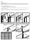
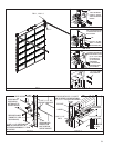
VERTICAL TRACK ADJUSTMENT
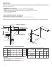
Adjust the spacing of the vertical tracks from 3/8”-5/8” spacing at the bottom section to 3/4”-7/8” spacing at the top section; refer to page 3. Permanently secure each vertical track to the
jambs.
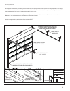
HORIZONTAL TRACKS/ ADJUSTING TOP BRACKET
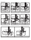
Use chain or cable to temporarily suspend the rear of the horizontal track assembly. Align the curved end of the horizontal track assembly with the top of the vertical track. Secure the
horizontal track to the splice plate or fl agangle using (2) 1/4” x 9/16” track bolts and hex fl ange nuts as shown in FIG L-4. Secure the horizontal reinforcing angle to the wall angle using (1)
3/8” x 3/4” truss bolt and nut as shown in FIG L-3; ignore the counterbalance hardware in this illustration; this hardware will be installed in the next step.
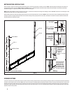
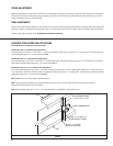
With tracks installed you can adjust the top brackets. Starting on one side, slide the top bracket roller(s) out against the horizontal track. Maintaining the slide’s position, tighten the
5/16” x 3/4” carriage bolt(s) and fl ange hex nut(s) to secure the top bracket slide(s) to the top bracket base. Repeat for other side.
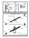
COUNTERBALANCE
INSTALL SUPPORT BRACKETS TO SOLID STRUCTURAL MEMBERS ONLY. DO NOT INSTALL OVER DRY WALL OR PANELING. FAILURE TO INSTALL SUPPORT BRACKETS TO SOLID
STRUCTURAL MEMBERS CAN CAUSE SEVERE OR FATAL INJURY.
FAILURE TO USE PROPER NUMBER OF FASTENERS CAN RESULT IN SUDDEN SPRING TENSION RELEASE, CAUSING SEVERE OR FATAL INJURY.
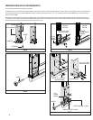
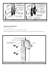
NOTE: Spring pads must be securely anchored before proceeding, as shown in FIG M-2. The pads must by fl ush with the jambs.
Attach the EBF’s (end bearing brackets) to the horizontal reinforcing angles using (2) 3/8” x 3/4” truss bolts and nuts, as shown in FIG L1, L2, L3.
Attach the EBF’s to the jambs using (2) 5/16” x 1-5/8” lags (wood), (2) 5/16” x 1” self-drilling and tapping screws (steel), or (2) 3/8” x 3” sleeve anchors (precast) (anchors by others).
Install the Center Support Bracket(s) to the spring pads at the same elevation as the bearing in the EBF’s. Depending on the construction different fasteners must be used.
Steel: Secure each center support bracket using (3) 5/16” x 1” self-drilling and tapping screws as detailed in FIG M-3.
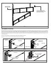
Pre-Cast: Secure each center support bracket using (2) 1/2” x 3” sleeve anchors (by others). This installation will require the 1/2” anchors to be secured to the building, then securing the
brackets to the anchors as detailed in FIG M-4.
Block Construction: Attach perforated angle 18” long to center support bracket(s) using (2) 3/8” x 1-1/4” bolts and nuts. Chamfer angle to clear top section high arc. Secure center
support bracket(s) and perforated angle to block using (4) 3/8” x 2-1/2” sleeve anchors as detailed in FIG M-1.
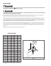
For 6” Springs: Attach DSB wall angle(s) to the spring pads. Fasten the spring plate to the wall angle bracket, as shown in FIG P.
NOTE: 1” GRADE 5 bolts are provided and must be used with the fl at and locking washers, to fasten the spring plate to the DSB wall angle.
NOTE: Additional center support brackets are not required for coupler support.
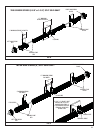
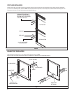
Torsion spring assemblies:
Torsion spring assemblies can be of several confi gurations depending on door size and weight. Left or right hand spring(s) must be identifi ed by the color of the winding cone (Refer to
FIG N, O and P. Ensure that spring warning tags are securely wired to all stationary spring cones.
NOTE: All red winding cone springs will be on the left side and all black winding cone springs will be on the right side.
NOTE: All set screws on drums and winding cones are painted red.
Locate torsion shaft and lay it in front of door on garage fl oor. Assemble torsion shaft assembly components according to spring and torsion shaft type as shown in FIG N, O, and P.
For 2” or 2-5/8” Spring(s) (Tubular Shaft Only): Install the loose steel bearing onto shaft (1 per spring(s)) and insert into stationary cone.
For 2-5/8”, solid shaft with coupler, 1 spring per bracket or 3-3/4” springs: Install the loose steel bearing onto shaft (1 per spring) and insert into the stationary cone. NOTE: Additional
center support brackets are not required for coupler support.
Lift the torsion shaft assembly into place by placing one end of the shaft into the end bearing bracket followed by the other end. Make sure the torsion shaft assembly and it’s components
are positioned properly with respect to the end and center support brackets, as shown in FIG N, O and P. The torsion shaft should be level and held in place by the end and center support
bracket(s). Secure the spring stationary cone(s) (dead end) to the center support bracket(s) using 3/8” bolts and nuts. Keep spring warning tags clearly visible.
NOTE: The center support brackets require (2) fasteners in the lower slot and hole, then (1) fastener in the top slot.
NOTE: Each 3-3/4”, 6” and Duplex spring is secured to a separate center support bracket. DO NOT attach two springs of this size to one center support bracket.
WARNING
WARNING