


2
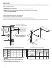
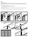
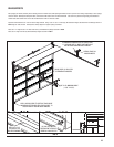
Dim. Y INDICATES THE DISTANCE FROM THE HEADER TO THE CENTER LINE OF
TORSION SHAFT.
NOTE: 2 1/2” OF ADDITIONAL HEADROOM IS REQUIRED FOR SINGLE TROLLEY
OPERATOR INSTALLATIONS.
NOTE: HEADROOM CAN BE REDUCED 2-1/2” BY USING THE QUICK CLOSING TOP
FIXTURE OR BY SHORTENING THE VERTICAL TRACKS BY 3” MAX.
TRACK
SIZE
MANUAL DEPTH
INTO ROOM
DIM. A
SIDEROOM TRACK
DIM. B
SIDEROOM
TORSION SHAFT
STEEL
MASONRY
AND WOOD
SOLID TUBE
2”
DOOR HEIGHT
PLUS 18”
MOTOR PLUS 66”
3-1/2” 4” 10” 5”
3”
DOOR HEIGHT
PLUS 24”
MOTOR PLUS 66”
4” 5” 10” 5”
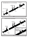
DRUMS DIMS
3” TRACK, 15”
RADIUS
2” TRACK, 15”
RADIUS
2” TRACK,
12” RADIUS
400-8,
400-12
HEADROOM
DIM Y
15-1/2”
13”
14-1/2”
12”
12-1/2”
9”
5250-18
HEADROOM
DIM Y
19”
14-1/2”
18”
13-1/2”
15”
10-1/2”
800-32
HEADROOM
DIM Y
21”
16-1/2”
20”
15”
17”
12-1/2”
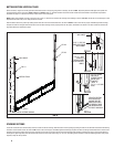
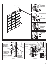
HEADROOM CHART For Standard Lift Track (Minimum Distance Required)
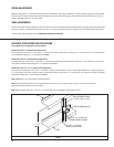
SIDE ROOM “A”
DAYLIGHT
OPENING HEIGHT
DAYLIGHT
OPENING WIDTH
BACKROOM
EXTEND JAMBS TO OPENING HEIGHT
PLUS DIM Y PLUS 1-1/2” (MINIMUM LENGTH)
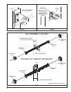
TORSION SHAFTS REQUIRE 10” OF
SIDEROOM FOR SOLID SHAFTS AND 5” OF
SIDEROOM FOR TUBULAR SHAFTS
MINIMUM HEADROOM
REQUIRED (REFER TO
HEADROOM CHART)
WALL ANGLES CUT 3” OFF
FOR 12” RADIUS APPLICATIONS
BACKROOM CHART (Minimum Distance Required)
HEADROOM “Y”
SIDE ROOM “B”
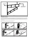
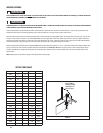
OPERATING ZONE
You Can Save Time And Effort If You First Establish All The Facts About The “Operating Zone”. The “ Operating Zone” is the area surrounding the door opening, extending upward and
backward as far as the door will travel. We call it the Operating Zone because it is the area that the door will have to operate within and the dimensions are critical and must be known in
advance of a door and operator installation.
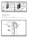
1. Daylight Opening: Exact size of fi nished opening.
2. Sideroom: required distance from the door opening to a wall or any obstruction. Refer To Sideroom Requirements.
3. Headroom: required distance from top of door opening to the ceiling or underside of joists. Refer To Headroom Chart.
4. Backroom: required distance from door opening header to the furthest back point to which the door track or operator unit, and their
brackets, will extend. Refer to Backroom Chart.
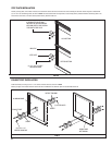
Verify the operating zone dimensions.
1 - Exact size of fi nished daylight opening. Do you have the correct door size?
2 - Sideroom requirements for track and spring shaft. (Refer to sideroom chart)
3 - Headroom requirements. (Refer to headroom chart for standard lift track)
4 - Backroom (depth into room) Manual lift = Door height plus 18” ; Operators = Door height plus 48” (Standard Lift)
5 - Jambs must be plumb and solidly attached to the building. Floor must be level or exact gradeline established before you start.
Shipping tags show important information, door size, track size and type, spring size and hardware type. Verify that all material is present and correct before attempting installation.
DIM “Y” HEADER
TO SHAFT
CENTERLINE
8” FOR 2” TRACK
12” FOR 3” TRACK