


14
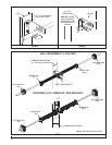
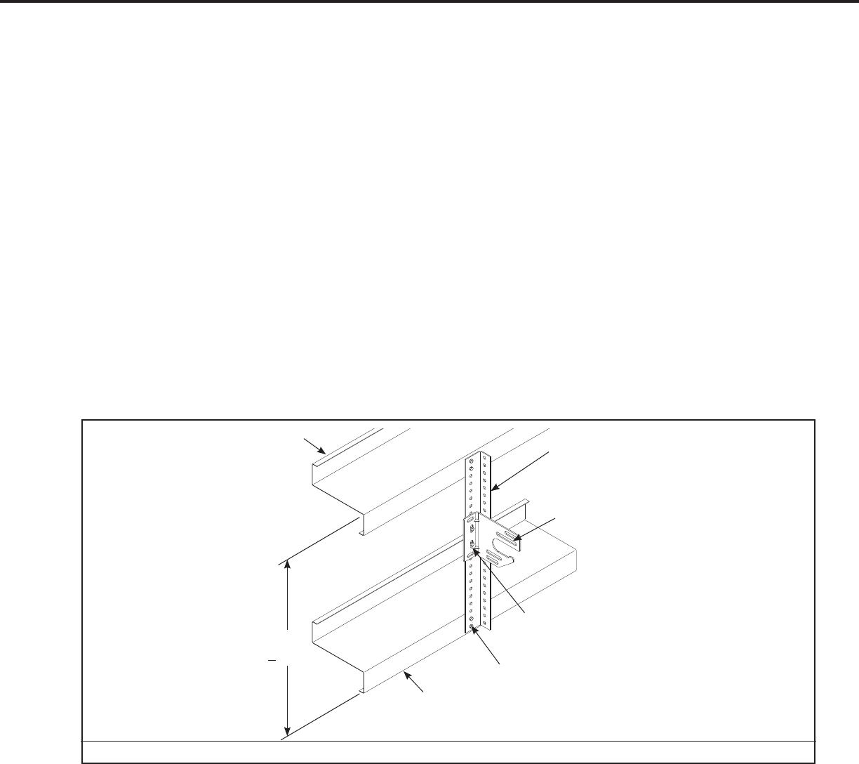
FIG S
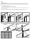
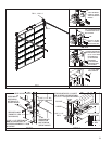
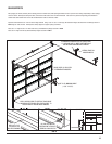
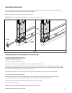
SPRING ADJUSTMENTS
Release the locking pliers from vertical tracks and check the door’s counterbalance. Adjust springs if necessary. If door does not balance properly, verify that all supplied
components such as struts are installed. Verify quantity, wire diameter, spring size & drums to the spring tag. Check Cable length. Add or subtract up to one turn on the
springs. Contact Wayne-Dalton Corp. if problem persists.
FINAL ADJUSTMENTS
Vertical tracks can now receive fi nal adjustments. Open and close the door a few times, checking and adjusting side clearance (if necessary). Tighten jamb fasteners (lags,
self drilling, or anchors) to permanently secure verticals. Adjust door in or out from jamb by loosening the track to obtain proper seal. Permanently tighten all track bolts.
Lubricate springs, rollers, and bearing with oil. DO NOT GREASE THE INSIDE OF THE TRACK.
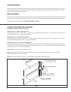
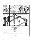
(2) 3/8” X 1-1/4” BOLTS TO
SECURE BRACKET TO ANGLE
HEAVY PERFORATED ANGLE
(1-5/8 X 2-3/8” X 11 GA.)
CENTER SPRING BRACKET
GIRT
(2) 3/8” X 1-1/4” BOLTS
& NUTS TOP & BOTTOM
GIRT
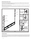
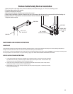
ALTERNATE STEEL SPRING PAD APPLICATIONS
Contact Manufacturer For Applications Not Covered Below
Maximum Door Size 9’ x 9’ (Maximum Door Weight 210 lb.)
Cut perforated angle (1-5/8 x 2-3/8” x 11 GA.) to Dim “Y”. Thru-bolt top and bottom of angle to each girt using (4) 3/8” x 1-1/4” bolts and nuts. Thru-bolt center bracket
to perforated angle using (2) 3/8 x 1-1/4” bolts and nuts (See FIG S).
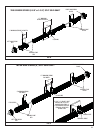
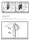
Maximum Door Size 14’ x 12’ (Maximum Door Weight 400 lb.)
Cut (2) perforated angle (1-5/8 x 2-3/8” x 11 GA.) to Dim “Y”. Thru-bolt top and bottom of each angle to each girt using (4) 3/8” x 1-1/4” bolts and nuts. Thru-bolt each
center bracket to perforated angle using (2) 3/8 x 1-1/4” bolts and nuts (See FIG T).
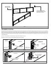
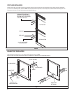
Maximum Door Size 14’-2” x 12’-1” (Maximum Door Weight 800 lb.)
Cut (2) pieces of perforated angle (1-5/8 x 2-3/8” x 11 GA.) to Dim “Y” and (2) more pieces at Dim “Y” minus 3. Bolt the angles together into a “Z” shape using (4) 3/8” x
1-1/4” bolts and nuts. Thru-bolt top and bottom of each “Z” shaped angle to each girt using (4) 3/8” x 1-1/4” bolts and nuts. Thru-bolt each center bracket to perforated
angle assembly using (2) 3/8 x 1-1/4” bolts and nuts (See FIG U).
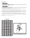
NOTE: Do NOT Bolt (2) 3-3/4” Torsion Springs To ONE Center Bracket
NOTE: These spring mounting techniques are not supported for 800-32, 6375-164, 1100-18, 1350-28, & 800-120 drums. These instructions are also not
applicable for 5750-120 drums with 72” Or more high-lift
NOTE: Maximum spacing for dimension “Y” is 84 in. (7 ft.) These instructions are not applicable for a span greater than 84 in.
“Y”
(< 7 FT.)