


6
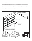
BOTTOM SECTION/ VERTICAL TRACK
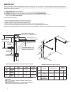
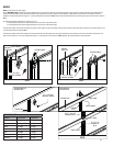
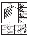
Center and level (or support to a known grade level) the bottom section in the opening, using shims if necessary, as seen in FIG H. Temporarily attach the wall angles to the jambs with
the appropriate lag screws, as shown in FIG H-1, FIG H-2 and FIG H-3. Allow 1/2” clearance between the section and the vertical tracks as illustrated in the sidereoom requirements
illustrations on page 3. It is important that the top of each track is on the same plane.
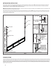
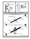
NOTE: Products being installed to precast or block must use a 3/8” x 3” sleeve anchor to attach the wall angle to the building, as shown in FIG H-3. Use the slots in the wall angle as a drill
template and drill a 3/8” hole (3-1/2” deep) and secure to anchor.
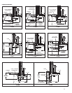
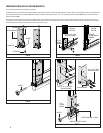
Stack the bottom section into position by hooking the left hand roller into the left hand vertical track, as shown in FIG H-4. Insert a roller into the proper, uninstalled right hand end hinge,
and place the roller into the right hand vertical track. Lower the roller and hinge into the proper position over the section, and attach to the section in the same manner the left hand end
hinge was attached, as described on page 5.
FIG H
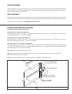
5/16” X 1” SELF
DRILLING &
TAPPING SCREW
FOR USE ON STEEL
JAMBS.
3/8” X 3” SLEEVE
ANCHOR (BY
OTHERS) FOR USE
ON PRE-CAST
CONCRETE.
( DRILL A
3/8” X 3-1/2” DEEP
HOLE)
5/16” X 1 5/8” LAG
SCREW FOR USE ON
WOOD JAMBS.
WALL ANGLE
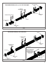
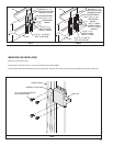
10”
24”
24”
O.C.
MAX
30” OR
18”
13”
NOTE: TYPICAL FASTENER SPACING.
24”
O.C.
MAX
FIG H-1
FIG H-2
FIG H-3
FIG H-1
FIG H-4
FIG H-2
FIG H-3
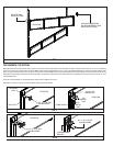
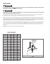
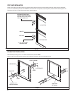
STACKING SECTIONS
Locate the Lock Section (the second section) and insert a roller into the left end hinge. Stack this section into the opening by hooking the roller into the left hand vertical track and lowering
the section onto the bottom section, as shown in FIG I. Insert a roller into the proper, uninstalled right hand end hinge, and place the roller into the right hand vertical track. Lower the roller
and hinge into the proper position over the section, and attach to the section in the same manner the left hand end hinge was attached, as described on page 5. Verify section alignment,
and fl ip up the upper hinge leaf(s) from the bottom section and secure to the lock section using 1/4”-20 x 7/8” self-drilling screws. Continue to stack the remaining sections in the proper
sequence, except for the top section.
WALL ANGLE
VERTICAL TRACK
FIG H-4
STACK THE SECTION
INTO POSITION, BY
HOOKING THE LEFT
HAND ROLLER INTO
THE VERTICAL TRACK
AND REPEATING FOR
THE RIGHT HAND SIDE.