


7
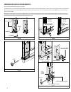
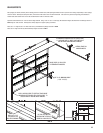
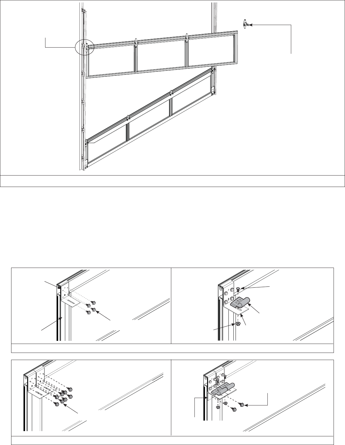
FIG J
(4) 1/4”- 20 X 7/8” SELF
DRILLING SCREWS
TOP BRACKET
BASE
END STILE
TOP SECTION
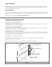
TOP SECTION
TOP
BRACKET
BASE
FLANGE HEX NUT
(1) 5/16” X 3/4”
CARRIAGE BOLT
TOP
BRACKET
SLIDE
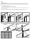
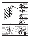
TOP BRACKETS/ TOP SECTION
Align upper-center hole of top bracket with vertical groove on the end stile and ensure top bracket is level and aligned with edge of top section. Secure with (4) 1/4”- 20 x 7/8” self drilling
screws, one in each corner of the top bracket, as shown in FIG J. Loosely fasten top bracket slide with (1) 5/16” x 3/4” carriage bolt and fl ange hex nut. Insert roller into slide. Repeat for other
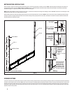
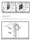
side. If your door has double end stiles then it will require 2 top brackets; as shown in FIG K, in which case an additional top bracket will be installed in the same manner next to the fi rst top
bracket with one roller being placed through both top bracket slides. 2 reinforcement brackets will then be installed under the 2 top brackets and secured to the section with (2) 1/4”- 20 X
7/8” self drilling screws.
If your door is trolley operated; it is recommended that an optional strut be installed on the top rail.
Now stack the top section, take care to ensure it is aligned properly with the other sections.
FIG K
(8) 1/4”- 20 X 7/8” SELF
DRILLING SCREWS
TOP SECTION
(2) 1/4”- 20 X 7/8” SELF
DRILLING SCREWS
(2) REINFORCEMENT
BRACKETS
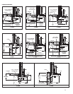
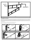
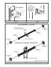
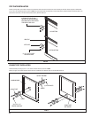
FIG I
LOCK SECTION
HOOK LEFT HAND
ROLLER INTO TRACK
SLIDE RIGHT ENDHINGE AND
ROLLER DOWN VERTICAL TRACK
AND OVER LOCK SECTION