


7
5. Add water to the brine tank (initial fill). With a
bucket or hose, add approximately 4 gallons
(15 liters) of water to the brine tank. If the tank has
a salt platform above the bottom of the tank, add
water until the level is approximately 1 inch (25 mm)
above the platform.
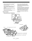
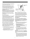
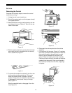
Figure 7 - Air Check
Open the water supply valve slowly to the fill open
position. Carefully rotate the camshaft
COUNTERCLOCKWISE
until the indicator on the
regeneration cycle indicator points directly to the
center of the
REFILL
position and hold there until the
air check (Figure 7) fills with water and water flows
through the brine line into the brine tank. Do not run for
more than two minutes. Rotate the camshaft
COUNTERCLOCKWISE
until the indicator points to
the center of the
BRINE/SLOW RINSE
position.
Check that water is being drawn from the brine tank.
The water level in the brine tank will recede very slowly.
Observe the water level for at least three minutes. If the
water level does not recede, if it goes up, or if air enters
the transparent air check chamber and the ball falls and
seats, refer to the
Troubleshooting
section in this
manual.
When the water is being drawn from the brine tank,
rotate the camshaft
COUNTERCLOCKWISE
until the
indicator points to
REGEN COMPLETE
. Run water
from a nearby faucet until the water is clear and soft.
Connecting the Control
The control has default values for most parameters that
were set at the factory, but there are key items that
need to be entered at the time of installation:
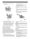
• Time of Day
• Time of Regeneration
• Hardness
• Salt Amount
• Capacity of the Unit
• Refill Controller Value
• Brine Draw Rate
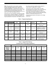
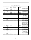
Determine from Tables 1 and 3 what these values
should be before applying power to the control. It is
also helpful to read the
Programming the Model 960
Control
section if you want to set other parameters.
When the conditioner is operational, complete the
following steps to connect the Model 960 control:
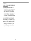
• Connect the control to the wall transformer
cable. The power connection is located on the
underside of the control on the left side (refer to
Figure 1). Insert the barrel style connector into
the power plug.
• Plug the wall-mount transformer into an
electrical outlet that is not controlled by a wall
switch.
• If the cord length of the transformer is too short,
an optional 15-foot low voltage extension cord
may be purchased (contact your original
equipment dealer for details) or the wire may be
spliced as shown in Figure 19 on page 24.
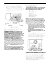
Figure 8 - Faceplate of 960 Control
Programming the Model 960 Control
This section covers all aspects of programming the
control. The control is shipped from the factory with
default values for Hardness and Capacity. These
default values will result in a system capacity of
100 gallons (1 cubic meter). While the control will
operate with these values, they should be changed to
meet the actual operating conditions.