


6
water pressure at the conditioner is not less than 40 psi
(2.8 bar). You may elevate an additional 2 feet (61 cm)
for each additional 10 psi (0.7 bar).
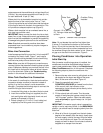
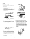
Where drain line is elevated but empties into a drain
below the level of the control valve, form a 7-inch
(18-cm) loop at the far end of the line so that the bottom
of the loop is level with the drain line connection. This
will provide an adequate siphon trap (Figure 5).
Where a drain empties into an overhead sewer line, a
sink-type trap must be used.
IMPORTANT:
Never connect the drain line into a drain,
sewer line, or trap. Always allow an air gap between the
drain line and the wastewater to prevent the possibility
of sewage being back-siphoned into the conditioner.
Note:
Standard commercial practices have been
expressed here. Local codes may require changes to
these suggestions.
Brine Line Connection
Install an appropriate fitting onto the 1/4-inch male NPT
connection on the air check, Figure 7, and install a
length of flexible tubing between the air check fitting
and the brine pickup tube at the brine tank.
Note:
Make sure that all fittings and connections are
vacuum tight so that premature checking does not take
place. Premature checking occurs when the ball in the
air check falls to the bottom before all brine is drawn
out of the brine tank. Refer to the
Troubleshooting
section in this manual for additional information.
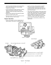
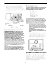
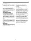
Brine Tank Overflow Line Connection
In the event of a malfunction, the brine tank overflow
connection directs overflow to the drain instead of
spilling it on the floor where it could cause water
damage. Complete the following steps to connect the
overflow fitting to the brine tank:
1. Locate the fitting hole on the side of the brine tank.
2. Insert the overflow fitting (not supplied) into the
tank and tighten with the plastic thumb nut and
gasket as illustrated in Figure 6.
3. Attach a length of 1/2-inch (1.3-cm) tubing (not
supplied) to the fitting and run to the drain.
Figure 6 - Overflow Line Connection
Note:
Do not elevate the overflow line higher than
3 inches (7.6 cm) below the bottom of the overflow
fitting. Do not tie into the drain line of the control unit.
The overflow line must be a direct, separate line from
the overflow fitting to the drain, sewer, or tub. Allow an
air gap as in the drain line connection, Figure 5.
Placing Conditioner into Operation
Initial Start-Up
After the water conditioning system is installed, the
conditioners should be disinfected before they are
used to treat potable water. Refer to the
Disinfection of
Water Conditioners
section in this manual. Complete
the following steps to place the conditioner into
operation:
1. Remove the rear valve cover by pulling back on the
tab located on the lower rear edge of the cover.
Next, lift the cover off the valve, Figure 10.
2. Grasp the camshaft and rotate it
COUNTERCLOCKWISE
(as viewed from the front
of the control) until the indicator on the
regeneration cycle indicator points directly to the
word
BACKWASH
.
3. Fill the mineral tank with water. Turn the water
supply off and place the bypass valve(s) into the
“not in bypass” position. Open the water supply
valve
very slowly
to approximately the 1/4 open
position.
IMPORTANT:
If the water supply valve is opened too
rapidly or too far, resin may be lost. In the
BACKWASH
position, you should hear air escaping slowly from the
drain line.
4. When all of the air is purged from the tank (water
begins to flow steadily from the drain), slowly open
the main supply valve all the way. Allow the water
to run into the drain until clear. Turn off the water
supply and wait for about five minutes to allow all
trapped air to escape from the tank.
Brine Tank
Overflow Fitting
Installed
Connect 1/2-in. (13 cm)
I.D. Tubing or Hose and Run
to Drain