


12
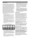
Brine Draw Value
Parameter P7 is used by the control to calculate the
brine draw time. The default value of 25 was selected
for a “B” injector with low water pressure or an “A”
injector with moderate water pressure. If this does not
match your installation, press the
SET
button and enter
a new value. Refer to Table 4 for the correct value. Find
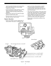
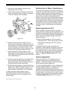
the injector used in the 255 valve. The injector cap is
labeled with the injector letter and the injector is color
coded for easy identification. Next, determine the
typical water pressure for this installation. The Brine
Draw Value is an estimate of the flow rate of brine
through the injector. This rate varies with water
pressure and injector type as shown in Table 4. The
control calculates the brine draw time using this value
and the salt amount. The brine draw time is added to
the Rinse Time (P10) to determine the total Brine
Draw/Slow Rinse Time.
• This control does not use Parameter P8. No entry
is needed for this parameter.
• Parameter P12 selects the units of measure. Be
sure that this is set to the correct value before
entering any data for Parameters P3, P4 or P5.
• Parameter P13 selects the clock display mode. If
the 12-hour mode is selected, a PM indicator is
used. If the 24-hour mode is selected, the PM
indicator is not used.
• Parameter P15 has four allowable values. Values 0
or 1 will cause the control to wait for Parameter P2,
time of day of regeneration, to begin the
regeneration. Values 2 or 3 will cause the control to
start the regeneration as soon as the capacity is
exhausted.
• When Parameter P15 selects a variable reserve
type, 0 or 2, Parameter P16 is used to calculate the
initial seven average daily water usage values. The
control multiplies the total capacity by the
percentage entered for Parameter P16 and uses
that value as the initial average daily usage for each
day of the week until water usage establishes new
averages.
• Parameter 17 has two allowable values, 0 or 1,
however, the 1 is reserved for future options and
thus should not be used. Improper regenerations
will occur if P17 is set to 1.
• Parameter P18 allows the installer to lock the Salt
Amount and Capacity values so they cannot be
changed. When Parameter 18 is set to 1, those two
settings can only be viewed when the control is in
the Level II mode. The settings will be skipped
when the control is in the Level I mode. When
Parameter 18 is set to zero, the Salt Amount and
Capacity can be viewed and changed in either
Level I or Level II.
• Parameter P19 is used at the factory to enter
default values.
This parameter does not need to
be
changed
. Using this parameter will erase the
values for all other parameters and replace them
with default values.
Improper regenerations will
occur if P19 is set to a 1 or 3.
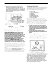
Regeneration
When the control begins a regeneration, the display will
alternate between Time of Day and Regen Time
Remaining. The Regen Time Remaining is shown in
minutes. The control will start and stop an internal
motor which drives the camshaft through the various
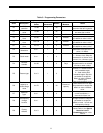
regeneration positions. The control uses the
information entered in the parameters shown in Table 3
to determine how long each part of the cycle should
last. The control will stop the camshaft at the correct
location for each part of the regeneration cycle.
If power fails during a regeneration cycle, the cycle
completes normally when the power is restored.
Note:
The
REGEN
button is only active when the
display is alternating between Time of Day and
Capacity. When programming Level I or II parameters,
the
REGEN
button is not active.
Conditioned water is available when the control enters
the brine refill cycle. The Regen Time Remaining in
regeneration will continue to count down until the
indicator points to
REGENERATION COMPLETE
.
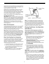
Manual Regeneration
To force the control to perform a regeneration, press the
REGEN
button. This button is located on the front of
the control. When you press the
REGEN
button, the
control performs a full regeneration of the conditioner.
If you press this button again more than one minute
after regeneration begins, but before the
regeneration is complete, a second regeneration
will start when the first regeneration is finished.
The
display will freeze and only show the Regen Time
Remaining as an indication that the second
regeneration will be performed. When the first
regeneration is complete, the second one will begin
and the display will alternate between Time of Day and
Regen Time Remaining.
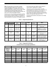
Table 4 - Brine Draw Value
Injector Color
Brine
Draw
Value at
30 psi
Brine
Draw
Value at
50 psi
Brine
Draw
Value at
70 psi
A White 19 26 31
BBlue24 30 37
C Red 29 37 40