


Cleaning the piston rod
1. Remove the cylinder from the vise.
2. Position the piston rod assembly in the vise and tighten.
The piston rod may be damaged if you are using a vise
with steel jaws. Use a vise with aluminum jaws or take
precautions to protect the piston rod.
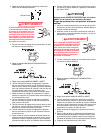
3. Remove the jam nut (21).
4. Remove the retaining nut (20).
5. Remove the outlet valve seat (18), the outlet ball (17), the
seal washer (19) and the outlet ball cage (16). Inspect the
outlet valve ball and the outlet valve ball seat for damage.
If the seat is worn or damaged, it can be flipped to the
unused side. If you flip or replace the seat, the ball must
be replaced.
6. Remove the lower packings (12, 13), the pressure ring
(11), and the wave washer (9).
7. Soak the new leather packings in linseed oil for 5 minutes.
Do not over-soak.
8. Clean the disassembled parts in an appropriate solvent.
9. Install the outlet ball cage (16), the outlet ball (17), the
outlet valve seat (18) and the seal washer (19), in that
order into the piston rod.
10. Apply removable threadlocking compound to the retaining
nut threads (20) and screw the retaining nut into the
piston rod. Torque the retaining nut to 250 in./lbs.
11. Apply removable threadlocking compound to the jam nut
threads (21) and screw the jam nut onto the retaining nut.
Torque the jam nut to 200 in./lbs. Remove the piston
assembly from the vise.
Replacing the packings
1. Position the wrench flats of the cylinder (8) into the vise
and tighten the vise.
2. Insert the wave spring (6), pressure ring (5), upper
packings (3, 4) and adapter (2) into the cylinder (8).
3. Loosely thread the packing nut (1) into the cylinder.
4. Remove the cylinder from the vise, rotate it and replace it
in the vise so that the bottom of the cylinder is facing up.
5. Insert the wave spring (9), the lower pressure ring (11),
lower packings (12, 13), the lower ring support (14) and
the O-ring (22) into the cylinder.
Inserting the piston rod
1. Insert the piston rod assembly into the cylinder.
2. Insert the O-ring (27) into the inlet valve housing (28).
3. Insert the inlet ball seat (26) and the inlet ball (24) into the
inlet valve housing.
4. Insert the stop disk (23) into the inlet ball cage (25) and
place them into the inlet valve housing (28).
5. Thread the inlet valve housing assembly onto the bottom
of the cylinder assembly. Torque to 40 ft./lbs.
6. Install the large locknut (7) onto the cylinder and turn it
until the nut bottoms out on the threaded section of the
cylinder.
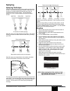
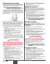
NOTE: Make certain to alternate the UHMWPE and
leather packings as shown in the illustration.
CAUTION
10 © SprayTECH Corporation. All rights reserved.
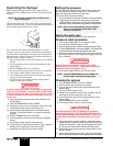
Attaching the fluid section
1. Remove the assembled fluid section from the vise. Apply
anti-seize compound on the upper cylinder threads and
thread it into the pump housing. The piston rod (10) will
align itself with the slide block.
2. Rotate the fluid section so that the hole in the slide block
is aligned with the hole in the piston assembly.
3. Slide the connecting pin through the holes in the slide
block and the piston assembly.
4. Replace the cotter pin to hold the connecting pin securely.
Refer to the illustration on the previous page.
5. Screw the fluid section into the pump housing as far as it
will go. Then unscrew it slightly so that the outlet elbow
will align with the fluid hose.
6. Firmly tighten the locknut (7) by turning it clockwise until it
is secured tightly against the drive housing.
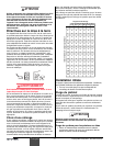
Repair kits
Item Part No. Description Qty.
1 0279910 Packing kit
(Includes those items marked with an *) ..........1
2 0294689 Inlet valve kit
(Includes those items marked with a +)............1
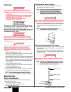
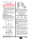
Replacing the motor brushes
Brushes should be inspected periodically for wear. If one of
the brushes measures less than 1/2", is worn or is chipped,
then replace both of the motor brushes. It is recommended
that the brushes be replaced when the packings are replaced.
ALWAYS follow the PRESSURE RELIEF PROCEDURE
found in your manual before starting any troubleshooting,
servicing or cleaning.
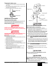
Removing the motor cord
1. Disconnect the power cord from the electrical supply.
2. Loosen the 4 hex socket head allen screws along the
sides of the motor cover and remove the cover.
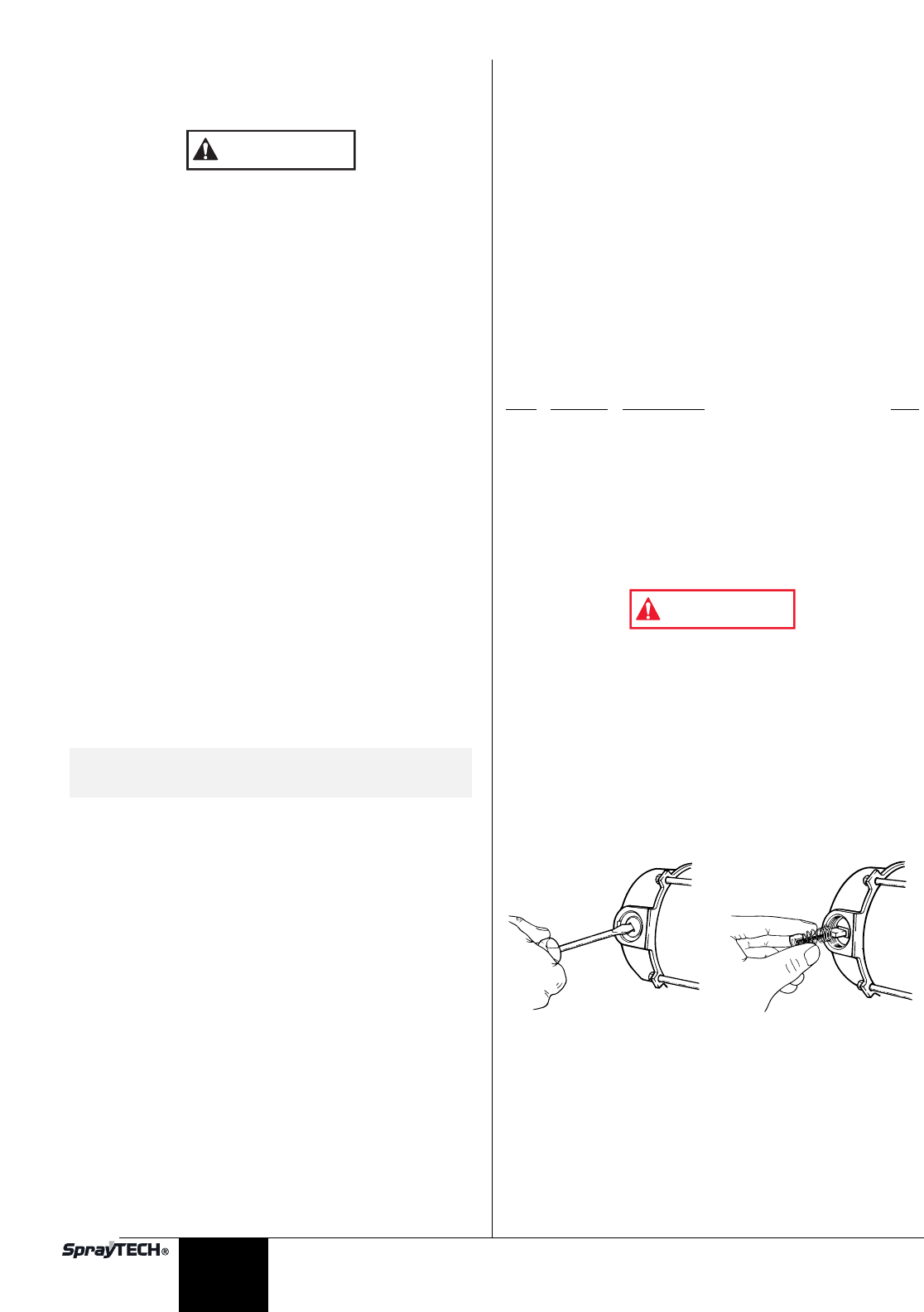
3. Unscrew and remove the brush caps holding the brushes
in place.
4. Pry the brushes out gently with a screwdriver.
5. Install the new brushes, P/N 01694.
6. Install the brush caps. If the old brush caps are damaged,
replace them with P/N 01686.
7. Replace the motor cover and hex socket head allen
screws.
WARNING
English