


TECHNICAL SUPPORT 1 800 908 0884
23
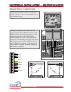
ACCESSORY CONNECTIONSACCESSORY CONNECTIONS
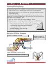
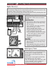
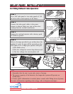
When connecting the Radio Receiver carefully verify the proper connections.
The maximum voltage that the control board provides for external accessories is the
maximum voltage of the battery, which is about 28 volts.
In the event of an electrical short the board will protect itself by shutting down and
will remain shut down until the short is corrected.
Radio Receiver
Radio Station
Mag.
Lock
Mag. Lock
Safety ConnectorOpen CommandsGuard StationMaster/Slave
Brake
UL
Siren
Radio
Rec.
UL
Sensor
OPEN RIGHT
24V BAT 24VAC
OPEN LEFT
Safety
Loop
Center
Loop
Obstruction
S
ensor
Charger
Power
Low Battery
Motor Sensor
Hold Open
Timer
Stop
Overlap Delay
Close Open
Obstruction
Sensor
min. MAX
Overlap
Delay
1.5
0
3
Radio StationLoop ConnectorOpen CommandsGuard StationMaster/Slave
GND
Close
Stop
Open
GND
Close
Stop
Open
Gnd
Fire
Gnd
Strike
Gnd
Exit
Gnd
Center
Gnd
Reopen
Gnd
UL
Gnd
+28v
Gnd
Radio
Gnd
+28v
+28v
Mag.
Lock
F
ail
Safe/Secure
MAG. LOCK
N.C.
COM
N.O.
Charger
Power
Low Battery
Motor Sensor
Hold Open
Timer
Stop
Close
Open
30
60
Off
1
Radio
Rec.
UL
Sens
Safety
Loop
Center
Loop
Brake
Siren
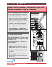
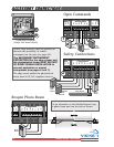
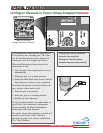
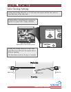
The control board provides two modes of
operation that a radio receiver can control
the gate:
Open-Stop-Close
1. By having the radio receiver connected as
illustrated and with the Hold Open Timer
OFF (see below):
Every command of the radio transmitter
will control the gate as follow:
a) First command opens the gate,
b) Second command stops the gate and
c) Third command closes the gate
d) Any subsequent commands will continue
in the same order to control the gate.
This type of configuration is not
recommended for a commercial
installations.
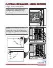
Open Only
2. By having the radio receiver connected as
illustrated and with the Hold Open Timer
ON (see below):
Each command of the radio transmitter is
ALWAYS AN OPEN COMMAND to the gate.
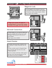
External
Accessories
COM
NO
Gnd
+24VDC
Radio Station
Mag.
Lock
Mag. Lock
Safety ConnectorOpen CommandsGuard StationMaster/Slave
Brake
UL
Siren
Radio
Rec.
UL
Sensor
OPEN RIGHT
24V BAT 24VAC
OPEN LEFT
Safety
Loop
Center
Loop
Obstruction
Sensor
Charger
Power
Low Battery
Motor Sensor
Hold Open
Timer
Stop
Overlap Delay
Close Open
Obstruction
Sensor
min. MAX
Overlap
Delay
1.5
0
3
Radio StationLoop ConnectorOpen CommandsGuard StationMaster/Slave
GND
Close
Stop
Open
GND
Close
Stop
Open
Gnd
Fire
Gnd
Strike
Gnd
Exit
Gnd
Center
Gnd
Reopen
Gnd
UL
Gnd
+28v
Gnd
Radio
Gnd
+28v
+28v
Mag.
Lock
Fail
Safe/Secure
MAG. LOCK
N.C.
COM
N.O.
Charger
Power
Low Battery
Motor Sensor
Hold Open
Timer
Stop
Close
Open
30
60
Off
1
Radio
Rec.
UL
Sens
Safety
Loop
Center
Loop
Brake
Siren
2
1
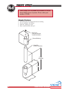
Hold Open Timer
1
2
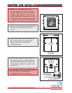
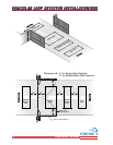
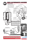
Connection Locations
(Single Unit Board shown)
The Hold Open Timer function holds the gate at
the open position for a predetermined amount
of time, prior to closing automatically.
Set the Timer to the desired time, from 1 to
60 seconds.
If this feature is not needed, turn the Trim
Pot clockwise to the “off” position.
Note: The Hold Open Timer affects the “radio
receiver command” and the sequence of
operation for the gate (see page 23).