


TECHNICAL SUPPORT 1 800 908 0884
12 16
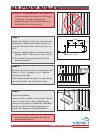
STEP 1
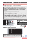
Check the integrity of the gate structure and
sufficiently sturdy such as pivot points are
properly lubricated and surfaces are free of
rust.
a) Remove the Motor/Gear Assembly from its
package. NOTE - The cover is not secured.
b) Disassemble the geared motor from the
mounting chassis.
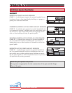
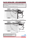
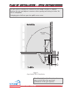
STEP 2
Position the pivot bracket in accordance with
figure A, B or C on page 10 or 11 and the
drawing at the right.
Tack weld the bracket in place. For non-ferrous
gates the bracket can be bolted in place.
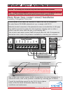
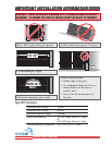
STEP 3
Chassis Installation:
Chassis can be welded to the gatepost. In the
case of a non-ferrous post, anchoring the
chassis may require an additional embedded
bracket or special anchoring hardware to
ensure the longevity of the installation.
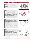
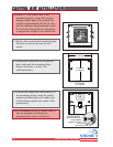
14.173"
5.90"
3.937"
5.90" 1.181"
Motor/Gear Chassis
1-1/2"
GATE OPERATOR INSTALLATIONGATE OPERATOR INSTALLATION
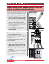
CAUTION - If mounting bar is not welded to
a frame member that runs the full length
of the gate, the gate operator may
damage the gate. Do not weld the bar or
backing plate to a few pickets.
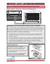
Note: Depending on type of anchor used, it
may be required to enlarge the holes in
the mounting chassis.